Continue to Site

Welcome to EDAboard.com

Welcome to our site! EDAboard.com is an international Electronics Discussion Forum focused on EDA software, circuits, schematics, books, theory, papers, asic, pld, 8051, DSP, Network, RF, Analog Design, PCB, Service Manuals... and a whole lot more! To participate you need to register. Registration is free. Click here to register now.

K3567 transistor workout...

Status
Not open for further replies.

Genovator

Advanced Member level 2
Joined
Dec 19, 2011
Messages
550
Helped
87
Reputation
174
Reaction score
84
Trophy points
1,328
Location
India
Activity points
4,632
Hi edaboard...

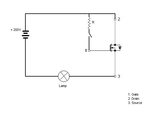
I am having a confusion on a transistor K3567 about the voltage flow....

Pin 1 is GATE which makes the circuit on & off....

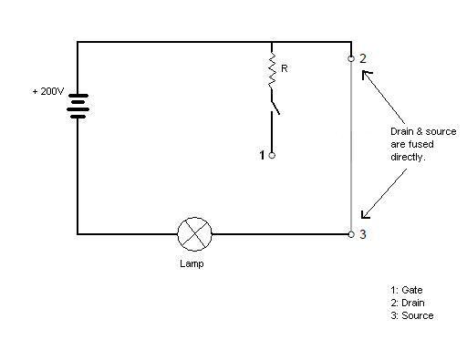
But I want to know whether the voltage flows from 'SOURCE to DRAIN' or 'DRAIN to SOURCE'????

Please simplify it.....
 

Last edited:

Thanx.... It cleared my confusion.....

Then should I conclude that the voltage flows from source to drain??????
 

Voltage doesn't flow, current does. :)
 

If it is a N-channel MOSFET:

Source to the ground, drain to Vcc through load.
 
Thanx.... It cleared my confusion.....

Then should I conclude that the voltage flows from source to drain??????

Since current flows from drain to source, the drain must be at a potential greater than the source. So, the drain has to be positive with respect to the source. Therefore, you connect the load between +ve and drain and source to ground.

You may connect the drain to +ve and the load between the source and ground. However, in this situation the drive becomes complex, as you need "high-side" drive.

Hope this helps.
Tahmid.
 
Thank you "etmabreu" and "Tahmid"......
You really helped me.....
Now I am confident on what I wanted to do....
------------
One last question I would like to ask before I close this thread...

=> If this transistor is working as a switch, then can I remove the transistor from the circuit board and fuse the DRAIN & SOURCE terminals together in order to remove the 'switch' factor....
Example diagram is shown below....
*********


The above circuit is modified into below....


The DRAIN & SOURCE is connected and the circuit is always ON. The switch becomes obsolete.

Will this circuit still works. (The regulator switching technique is not important for me)
 

If the drain and source are connected directly by external wiring then it becomes a short. It's no longer a switch - it is just a short.

In the first circuit you showed, you must connect a resistor between the gate and the source. The MOSFET has a small gate capacitance and if the gate is not pulled low, that capacitance isn't discharged. The MOSFET has an insulated gate. So, to turn it off, you must discharge the gate capacitance and apply logic 0 to the gate, just removing the positive supply won't do.

Hope this helps.
Tahmid.

- - - Updated - - -

PS. The gate has a maximum allowable voltage (with reference to the source). Usually this is 20V or 30V. So, in the circuit shown, you're connecting the gate to +200V. This would damage the MOSFET.
 

Yes, I dont want to turn it off.... As in the 1st line you mentioned, I want to short the drain and source... I dont want the switch (transistor). Will it work or not??????
 

It will just be a short. So, it will work. But why use a MOSFET at all, then? It's a good as a piece of wire.
 

Actually, the mosfet exists already in the circuit of an adapter and it is being drived by an ic NCP1203 (pin 5 to gate). I dont know why this ic is not providing voltage to the gate. My whole circuit is off. I found that this combination of ic & transistor is only for a security reason. So I thought to take a risk and remove this combination to make the circuit simpler....
My circuit was done modifying yesterday & I was waiting for your suggestion.....
 

Well, if you short the MOSFET drain and source, expect some burnt components and maybe some smoke.

The NCP1203 is the PWM controller that also features protection. It doesn't keep the MOSFET continuously on. It sends pulses - by pulse width modulation (PWM). If the IC does not generate pulse, there may be some problem. Either there's a fault and so the chip doesn't generate output. Or some components are damaged and so circuit isn't functioning properly.

Hope this helps.
Tahmid.
 

Yes.... The fuse blown out....
thankgod I added a fuse before trying it...

Well... That idea didn't worked.... I will try something else...

Thank you very much!!!!
 

Status
Not open for further replies.

Part and Inventory Search

Welcome to EDABoard.com

Sponsor

Back
Top