Continue to Site

Welcome to EDAboard.com

Welcome to our site! EDAboard.com is an international Electronics Discussion Forum focused on EDA software, circuits, schematics, books, theory, papers, asic, pld, 8051, DSP, Network, RF, Analog Design, PCB, Service Manuals... and a whole lot more! To participate you need to register. Registration is free. Click here to register now.

Designing a filter for three-phase full wave rectifier

Status
Not open for further replies.

TripACT

Member level 3
Joined
Apr 2, 2012
Messages
56
Helped
3
Reputation
6
Reaction score
3
Trophy points
1,288
Activity points
1,739
I built a three-phase rectifier using 6 diodes (full wave rectifier), feeding from a three-phase transformer 400v line-to-line to 24v dc.
To filter out the result i'd use a filtering circuit. At first i'd guess an electrolytic capacitor connected on the output should sufficient.
I tried different ranges C but nothing could perform better than this.

I'm trying to figure how to improve the DC filtering to smooth out the result as much as possible.

Is there any better way to do it ?

Please note:
I don't want to use 6 phase rectifier.

The idea is to feed that 24V right into a BUCK Converter obtaining high efficiency.

The design is made with OrCAD Capture & PSPice A/D Simulation

Any help appreciated !

Gary
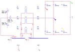
rectifier11.PNGrectifier12.PNG
 
Last edited:

- The output voltage of the bridge rectifier is the voltage across C1. It's not measured in your simulation circuit at all. PSpice has a voltage differential marker for this purpose.

- Alternatively, you can change the circuit ground from transformer star point to output V-.

- Without a load, the output voltage is just the input peak voltage. No realistic test setup for a filter. You should add a a load resistor or current source according to the intended output current.

- For a reasonable filter effect with usual output currents, the filter capacitor should be in a 1000 to 10000 µF order of magnitude.

- With a meaningful measurement setup, you'll see a 300 Hz ripple frequency.


Thanks. Changed the capacitor value to 1000uF.
I just tried it and used the differential probes on the capacitor and it now measures a nice DC.
BUT it shows ~41Vdc on the output. How come ?

EDIT: i just removed the capacitor and measured. Shows ~41Vdc again but with significant larger amount of ripples.
So the 41Vdc is the resulted voltage of the rectifier.
Is there any formula to know the combined voltage out of the rectifier's output ?

-Gary

rectifier13.PNG
 
Last edited:

Everything as expectable.By design, the unloaded DC output voltage of a three phase brdige is the peak value of the interphase voltage, sqrt(3)*Vpk,phase voltage.

You should add a load to see a more practical test case.
 
Hello! I am also designing a three phase full wave rectifier. Can you send me your circuit diagram of PsPice simulation and Proteus ISIS Simulation if you have which are final and working? I want to make the circuit for 220V AC to 220V dc for my project.
 

Status
Not open for further replies.

Part and Inventory Search

Welcome to EDABoard.com

Sponsor

Back
Top