Continue to Site

Welcome to EDAboard.com

Welcome to our site! EDAboard.com is an international Electronics Discussion Forum focused on EDA software, circuits, schematics, books, theory, papers, asic, pld, 8051, DSP, Network, RF, Analog Design, PCB, Service Manuals... and a whole lot more! To participate you need to register. Registration is free. Click here to register now.

dc-ac inverter using thyristors

Status
Not open for further replies.

pns2050

Junior Member level 1
Joined
Feb 29, 2012
Messages
17
Helped
0
Reputation
0
Reaction score
0
Trophy points
1,281
Activity points
1,423
Hello,

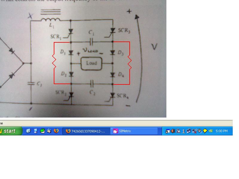
am trying to implement the topology below to invert from dc to ac..i am using thyristors to do that,but it seems i am not getting the results that i should.

when i trigger SCR1 and SCR4 respectivily everything seems fine , capacitors are being charged with the correct polarity
Also when i trigger SCR2 and SCR3 again capacitors are being charged with inverted polarity and also getting the correct output on my load..

But if SCR1 and SCR4 are on and i trigger SCR2 and SCR3 it seems that current flows directly to reference without passing through load.. It seems that i fail to Turnoff my thyristors while capacitors are discharging..

Any ideas what i may be doing wrong?

Thanks


Photo0450.jpg
 

I think you need to add a couple of resistors as in the pic below. That will help one pair of thyristors to turn off the other pair.

edit: Oops, sorry, forgot to crop the pic.:sad:


Thanks for the reply godfreyl,
i will try this tommorow when i ll be back to the lab.
 

I think you need to add a couple of resistors as in the pic below. That will help one pair of thyristors to turn off the other pair.

edit: Oops, sorry, forgot to crop the pic.:sad:


Godfreyl,

after i looked more closely your solution i failed to understand why this would help..
Can you explain how it should work please?

The thyristors should TURN OFF while the capacitors discharge .. If i put the resistors there dont i cancel out the job of diodes in the topology ?
 

The resistors shouldn't be required. The question is why you're unable to turn off the opposite branch? It may be a case of unsuitable component values or timing.

How do you check circuit operation?
 

How do you check circuit operation?

Hello FvM,

I trigger the thyristors using PIC1f871.. After i saw that the result was not what i should expect,

i tried triggering first SCR1 and SCR4 .. i remove the pulses and thyristors SCR1 and SCR4 stay on as expected.
then i send pulses to SCR2 and SCR3 and it seems the circuit short circuits.. the lamp turns off(LOAD)

i used oscilloscope to check my triggering and both pulses happen at the same time.
I also have a voltmeter checking capacitors polarity..

I really cant figure out whats wrong at the moment
 

How do you peform the level shift for the high-side thyristors?
 

i am not sure what you mean with that FvM, level shift for the high side? you mean the firing ?
 

Godfreyl,

after i looked more closely your solution i failed to understand why this would help..
Can you explain how it should work please?

The thyristors should TURN OFF while the capacitors discharge .. If i put the resistors there dont i cancel out the job of diodes in the topology ?
Looking at the top half:
When SCR3 fires, you need a pulse of current through C1 to momentarily steal SCR1's cathode current and switch it off.

To produce the current pulse through the capacitor, the voltage at SCR3's cathode needs to jump up instantly when it is fired. The resistor on the right helps hold the voltage on SCR3's cathode down when it is off, so that it can jump up 2 diode drops while SCR4 is still on.

Maybe the resistors aren't needed, but I thought they might help.
 

Godfreyl,

I have tried also with the resistors as in the picture you proposed but the result was the same.. SCR's fail to turn OFF when their respective SCR turns ON.

Any other ideas would be appreciated
 

I was interested in this subject about 25 years ago. As far as I remember, the turn off needs a sort of LC resonance (series resonance with C) to drop the current in the thyristor of interest to zero. At that time, I didn't have a good oscilloscope to check my works so I dropped this method and used BJT transistors instead (for the half and full bridges). Now I use MOSFETs

Thyristors are attractive for heavy loads but their turn off mechanism when working with DC is rather delicate but can be done.
 
Last edited:

level shift for the high side? you mean the firing ?
Exactly. Unsuitable level shift can cause a trigger delay and possibly failure in turning one of the thyristors off.

---------- Post added at 14:27 ---------- Previous post was at 14:15 ----------

As far as I remember, the turn off needs a sort of LC resonance (series resonance with C) to drop the current in the thyristor of interest to zero.
Yes, that's at least on one option. Also the shown circuit (that should basically work in my opinion) uses an LCcicrcuit, but not necessarly resonance.

I remember high frequency (10 - 20 kHz) thyristor inverters in a simple transformer push-pull configuration. A parallel resonance capacitor achieved turn-off. The inverter supplied a corona discharge unit for surface treatment of polyethylene films. Unfortunately, thyristor turn-off sometimes failed under unexpected operation conditions. The thyristors had been rugged enough to survive this situation, but the power supply fuse was blown.

Another popular thyristor DC/AC application is color TV horizontal and HV power stage, mostly used in the 70th.

These days, it's legacy except for MW high voltage applications.
 

The problem is likely insufficient capacitance (or voltage on the capacitors) to turn off the SCRs, or a problem with the triggering pulses like FvM suggests. Failing to trigger both SCRs at the same time will result in shoot through.
 

Thank you all for your replies,

The problem is likely insufficient capacitance (or voltage on the capacitors) to turn off the SCRs,..

I have tried and added 3 capacitors in parallel of 4,7μf (biggest i found in market) so i would say that the problem is elsewhere..

From what you people said here and watching how my circuit reacts it seems that indeed the problem has to be with the GATE triggering.

The pulses coming out of PIC are good , i used oscilloscope to check them and they both hit the gate terminal at the same time..

Now what i have noticed is that when i trigger one side of the circuit i get a pulse coming out of the gate of the opposite thyristor..
And to add to that another headache, the two thyristors that are ON have some voltage at the gate terminals returning it to my pic output pins.. probably this is what FvM was refering to level shifting..?
 

Post a schematic of how your PIC outputs are driving all four thyristors. You can't use the bare outputs to drive the gates directly, you at least need optoisolators or gate drive transformers for the upper devices.
 

Status
Not open for further replies.

Similar threads

Part and Inventory Search

Welcome to EDABoard.com

Sponsor

Back
Top