Continue to Site

Welcome to EDAboard.com

Welcome to our site! EDAboard.com is an international Electronics Discussion Forum focused on EDA software, circuits, schematics, books, theory, papers, asic, pld, 8051, DSP, Network, RF, Analog Design, PCB, Service Manuals... and a whole lot more! To participate you need to register. Registration is free. Click here to register now.

[SOLVED] Switched capacitors for generating a ramp

Status
Not open for further replies.

ruby1212

Junior Member level 3
Joined
Feb 28, 2010
Messages
31
Helped
1
Reputation
2
Reaction score
1
Trophy points
1,288
Location
France
Activity points
1,592
Hello all,
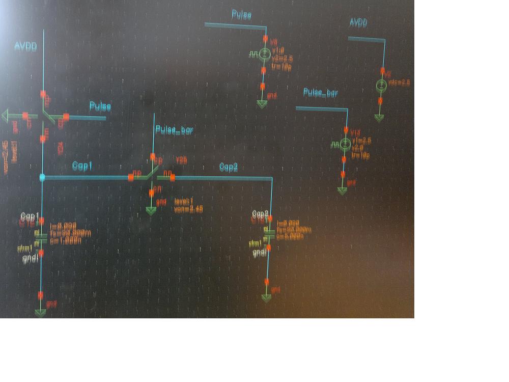
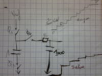
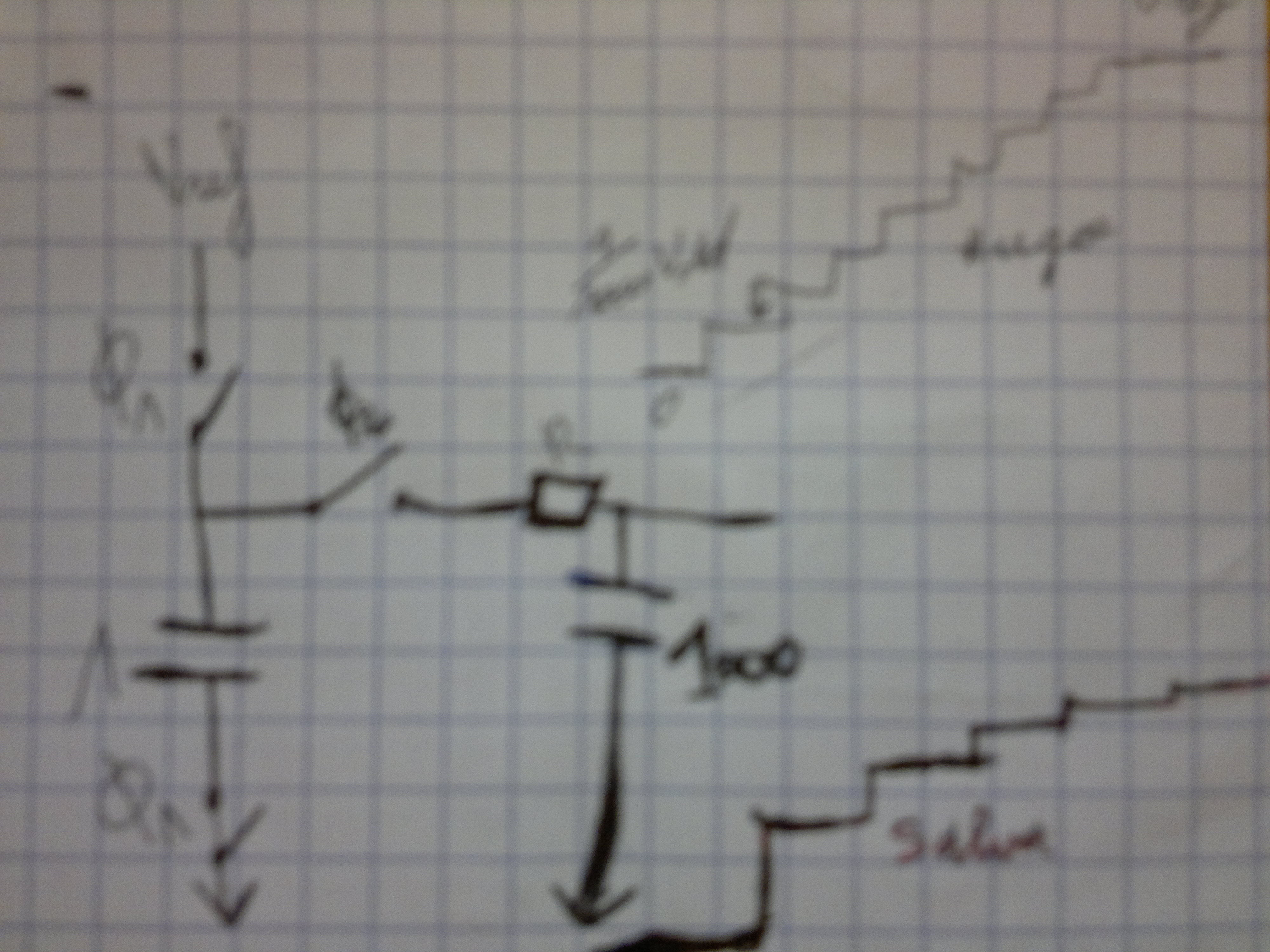
I am trying to simulate a very basic circuit but i don't know why it does not work. The goal is to generate a ramp.
Below the picture: the basic principle is to charge a small capacitor which will be "poured" step by step into a bigger one.

In my simulation i have two capacitors and i'm using an ideal switch "vswitch" from mgclib (no resistor on my schematic).
What should i verify in the circuit ? the capacitors do not charge at all. Why can a capacitor not charge if connected to VDD through an ideal switch ?
Why can a capacitor not charge if connected to VDD through an ideal switch ?
I am wainting for your answers. Please help.
Grazie !!
 

Your post is a very large and blurry picture.

The capacitors should charge. Show us the simulation.
 

Ok. I'm sorry for the blurry picture, i was not on cadence when i posted the message.
So here is a clearer (I hope) picture of my schematic. Ok i took it with my phone, print screen does not work on my station :(

When I connect a resistor to net "cap2" the capacitor connected to vdd charges and then discharges in the resistor. But this is not wha i want.
When I put 2 capacitors as shown in the schematic. There is no charge transfer between the two capacitors..This is supposed to be a switched capacitor circuit. The voltages of net "cap1" and net "cap2" are just stuck to Vdd. No matter capacitors values.
Why the capacitor connected to vdd does not charge anymore when i put a second capacitor ? why there is no charge transfer ??
 

There's a chance you need to put resistors inline with the caps, to keep the simulator happy.

Try adding a load to drain the second capacitor a bit. 100K or so.

Are your caps of equal value? After 1 cycle, they will each be at supply V / 2.
After that there is less noticeable rise/fall on either cap.
 
the image is still blur man , cant help until the picture is clear
 

Ok. I'm sorry for the blurry picture, i was not on cadence when i posted the message.
So here is a clearer (I hope) picture of my schematic. Ok i took it with my phone, print screen does not work on my station :(.............
Print Screen captures the screen image into the Clipboard memory. From there you have to Paste it into a graphics program such as Paint. Is that what you tried to do?
 

Ok. Thank you all guys. BradtheRad you're right adding some resistors keeps the simulator happy.
I found two solutions to my problem:
- charging the circuit with a very large resistor. (The simulator find it "easier" to find the initial conditions of the circuit if he sees a resistor somewhere instead of all capacitors and switches).
- Otherwise, keep only capacitors and switches and tell the simulator (command line) that he should start everything from zero (use initial condition).
So now the output is ramping as expected :)
PS. Crustschow I am simulating on linux through vnc and i tried to paste the captured screen on windows..I don't know why it did not work...i was in a hurry to look further why, so i just took the picture with my phone. Sorry for my laziness :D
 

Status
Not open for further replies.

Similar threads

Part and Inventory Search

Welcome to EDABoard.com

Sponsor

Back
Top