Continue to Site

Welcome to EDAboard.com

Welcome to our site! EDAboard.com is an international Electronics Discussion Forum focused on EDA software, circuits, schematics, books, theory, papers, asic, pld, 8051, DSP, Network, RF, Analog Design, PCB, Service Manuals... and a whole lot more! To participate you need to register. Registration is free. Click here to register now.

effect of optocoupler input signal current on circuit behaviour

Status
Not open for further replies.

sabu31

Advanced Member level 1
Joined
Jan 28, 2011
Messages
453
Helped
12
Reputation
24
Reaction score
13
Trophy points
1,298
Activity points
5,203
Hi
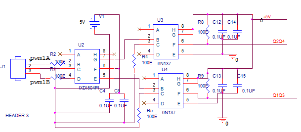
I am testing a single PHase H-Bridge inverter, the switches used are IRFPE50PBF and drivers is IR2110. THe dc link votlage is 400V, output 230Vrms, switching frequency =50Khz,Power level=250W.Output LC filter (L=8mH, C=9.3uF).The Pwm gating is given through an optocoupler 6n137.

I am finding that the resistance which I connect in the input side of optocoupler is affecting the entire circuit operation. If the current is less ( minimum required is 6mA) then the lower peak of output sine wave gets distorted and also the filter inductor makes humming noise (L=8mH, metglass core).Also inductor makes noise at higher power level as compared to lower level. However when the current into optocoupler (LED current) is increased,the waveform is perfect and inductor noise is also eliminated. Could somebody help me understand what is the reason and some references.

Thanking you.
 

Hi Sabu,

There is a distortion coming out of opto coupler, due to the time it takes for the LED to get to 2.4Vdc.
(or whatever the forward breakdown voltage is.) That is for when your LED is biased properly.

If you ramp up the I to the LED, and things get better, Then at the lower currents, the LED is not putting out enough light to
saturate the phototransister completely. If 6mA is the led min current, I would shoot for 15 mA.
-Lisa
 

Are you trying to drive the FETs directly with the optocoupler, or are the optocouplers driving other gate drive ICs? You should post the actual gate drive schematic.

Insufficient current in the isolators can cause several problems. Of most concern is the possibility that the turn off time of each FET will be increased greatly, leading to cross conduction in the H bridge.

There are several tricks one can use to increase the switching speed of optocouplers without simply resorting to higher driver currents. One simple way is using a "speed-up" capacitor like below:
11_1335960965.png


Lower circuit is normal resistive drive, while the upper circuit uses a speed up cap. The steady state current of both is the same, but the upper circuit will have faster switching times.
 

    V

    Points: 2
    Helpful Answer Positive Rating
Hi mtweig and LISA_DALTON

I have posted the schematic. The intial driver is a lowside driver which i am using as a buffer as the microcontroller can source only 4mA of current. The minimum current required by optocoupler is 6mA. THe output of the optocoupler goes to IR2110 which is a high-side nad low side driver . The maximum current capacity of driver is 2A.I have posted the schematic of optocoupler circuit

The resistance values are now arbitrary. The power suplly to IXDI504pI and 6n137 are seperate and isolated .
I am unable to understand the relation ship between the optocoupler current, inductor noise. Infact the microcontroller control gain is also getting affected. Some times i have to lower the control law gain and some times i can use higher. Could you explain how to calculate the resistance or give references. Also how is this affecting the control loop.. THanks
 

Could you explain how to calculate the resistance or give references.
For R4 and R5:
The output voltage from the IXDI504 is very close to 5V. The drop across the diode in the 6n137 is 1.4V typical, 1.8V max. So the voltage across the resistor is 3.6V typical, 3.2V minimum. R=V/I, so a 330 Ohm resistor will give about 10mA.

According to the 6n137 datasheet, 330 Ohms looks like a good value for R8 and R9 as well.
 

    V

    Points: 2
    Helpful Answer Positive Rating
You are facing problems at very high/low duty cycles (i.e. the maximum and minimum of your sinewave).

Switching times of your optocoupler depend on forward current and also output load (Fig. 3 https://www.fairchildsemi.com/ds/6N/6N137.pdf). The lower the output load resistance, the faster it will switch on. The higher the LED forward current the faster it will switch off.

Note that at 50 kHz 98% duty, the off time is 400 ns. If your optocoupler delays are about 200 ns you may be facing distortion of the applied PWM signal. At very high/low duty cycles this distortion is huge and causes bad system performance.

In addition IR2110 has a maximum duty cycle for proper bootstrap capacitor charge. If you do not leave enough time for the bootstrap capacitor to charge and the voltage falls below UVLO, the driver shuts down temporally.

Ernest

Hi emontllo
Note that at 50 kHz 98% duty, the off time is 400 ns. If your optocoupler delays are about 200 ns you may be facing distortion of the applied PWM signal. At very high/low duty cycles this distortion is huge and causes bad system performance.

I think that is where the problem is . I had check the system without L-C fitler and just put 50Khz 50%duty ratio to the bridge circuit and it was working fine. However when i give sinepwm, it gets heated very quickly (30 to 40seconds). How do i overcome this problem, i think 6n137 is fatest opto i could find.Is there any faster optocoupler.
I think may be i should reduce the modulation index, so that switches doesnt go to 98% duty. Any other methods to solve this problem? I also have a doubt whether IR2100 is capable of driving IRFPE50PBF which has a Qg of 200nC. Any thoughts on this..

THanks.
 

However when the current into optocoupler (LED current) is increased,the waveform is perfect and inductor noise is also eliminated.
It sounds like the circuit works perfectly if you increase the LED current. What is the remaining problem? Can't you just increase the LED current?
 

Hello,

various actions that would help improve the performance of your circuit:
- Reduce maximum duty cycle to a certain limit where your circuit works fine (i.e. use a modulation sine wave with less amplitude)
- Change optocupler to a faster one with logic output (speed will not depend on load) or use a digital isolator instead of optocoupler (ISOPro Series from Silicon Labs or iCoupler series from Analog Devices)
- Use another MOSFET. The one you are using is old and has a too high RDSon which means high power loses and also high gate charge. You can find 600 V rated MOSFETS (Ok with 400 VDC bus) with half the resistance and lower gate charge. These should reduce power loses and heating.
- IR2110 seems ok for your application 2 A peak should be enough. Reduce gate resistors if your commutation is too slow and want to reduce switching loses.

Ernest
 

    V

    Points: 2
    Helpful Answer Positive Rating
You are facing problems at very high/low duty cycles (i.e. the maximum and minimum of your sinewave).

Switching times of your optocoupler depend on forward current and also output load (Fig. 3 https://www.fairchildsemi.com/ds/6N/6N137.pdf). The lower the output load resistance, the faster it will switch on. The higher the LED forward current the faster it will switch off.

Note that at 50 kHz 98% duty, the off time is 400 ns. If your optocoupler delays are about 200 ns you may be facing distortion of the applied PWM signal. At very high/low duty cycles this distortion is huge and causes bad system performance.
This isn't necessarily true. If the PWM signals are simply delayed through the optocouplers and the rest of the signal chain, then that simply results in a delay of the sine wave, and no real distortion. That assumes the the delays are equal to each FET (should be the case if they're all driven with optocouplers), and that the delay of rising and falling edges is equal. That last part is probably not true, and may be the cause of the problem. Other than the gate signals, the FETs themselves may also have different rise and fall times. That can cause some distortion in the sine wave, but a much more serious problem is the possibility of cross conduction. I would try just looking at the gate signals and verify that there is adequate dead time (around 100ns) at extreme duty cycles.

Dropping the duty cycle range would also probably help as well. Raise the DC bus voltage a bit if you have to.
 

    V

    Points: 2
    Helpful Answer Positive Rating
Hello,

various actions that would help improve the performance of your circuit:
- Reduce maximum duty cycle to a certain limit where your circuit works fine (i.e. use a modulation sine wave with less amplitude)
- Change optocupler to a faster one with logic output (speed will not depend on load) or use a digital isolator instead of optocoupler (ISOPro Series from Silicon Labs or iCoupler series from Analog Devices)
- Use another MOSFET. The one you are using is old and has a too high RDSon which means high power loses and also high gate charge. You can find 600 V rated MOSFETS (Ok with 400 VDC bus) with half the resistance and lower gate charge. These should reduce power loses and heating.
- IR2110 seems ok for your application 2 A peak should be enough. Reduce gate resistors if your commutation is too slow and want to reduce switching loses.

Ernest

Analog Devices offers isolated gate drivers that would replace the two optocouplers and the gate driver IC in a much smaller package. Propagation delays for iCoupler products are up to 5x lower than for optocouplers and matching is much better. They’re also much easier to implement in a design since the inputs use standard digital logic and they don't suffer from CTR degradation.

Some gate drivers, such as the ADuM3220, have built-in shoot-through protection as well.

Other links you might find useful:

An Alternative to Optocouplers
https://www.analog.com/en/content/Optocoupler_Alternative_iCoupler/fca.html

iCoupler Digital Isolator Products
https://www.analog.com/en/interface/digital-isolators/products/index.html

Isolated Transceivers
https://www.analog.com/en/interface...ated_transceiver_portfolio/resources/fca.html

Interface Products
https://www.analog.com/en/interface/products/index.html


Last edited:

    V

    Points: 2
    Helpful Answer Positive Rating
THanks mtweig,Ernest,ADC_icoupler. I will implement some of suggestions you have given.. Thanks
 

iCouplers are quite interesting, EMC-wise they are not so much fun because you get a VHF generator "for free". This leads to the paradox situation that a straightforward design with low coupling capacitance and maximum air and creepage distances is thwarted by necessary EMC measures.
 

iCouplers are quite interesting, EMC-wise they are not so much fun because you get a VHF generator "for free". This leads to the paradox situation that a straightforward design with low coupling capacitance and maximum air and creepage distances is thwarted by necessary EMC measures.

A fair point - as we know, the engineering discipline is defined by trade-offs!

There are fairly straightforward techniques to mitigate EMC issues documented in this application note:

https://www.analog.com/static/imported-files/application_notes/AN-1109.pdf
 

Status
Not open for further replies.

Similar threads

Part and Inventory Search

Welcome to EDABoard.com

Sponsor

Back
Top