Continue to Site

Welcome to EDAboard.com

Welcome to our site! EDAboard.com is an international Electronics Discussion Forum focused on EDA software, circuits, schematics, books, theory, papers, asic, pld, 8051, DSP, Network, RF, Analog Design, PCB, Service Manuals... and a whole lot more! To participate you need to register. Registration is free. Click here to register now.

to design a dc-dc smps from 12v dc

Status
Not open for further replies.

Phyllis Mathenge

Newbie level 4
Joined
Mar 24, 2012
Messages
5
Helped
0
Reputation
0
Reaction score
0
Trophy points
1,281
Location
Nairobi, Kenya
Activity points
1,326
Hi,
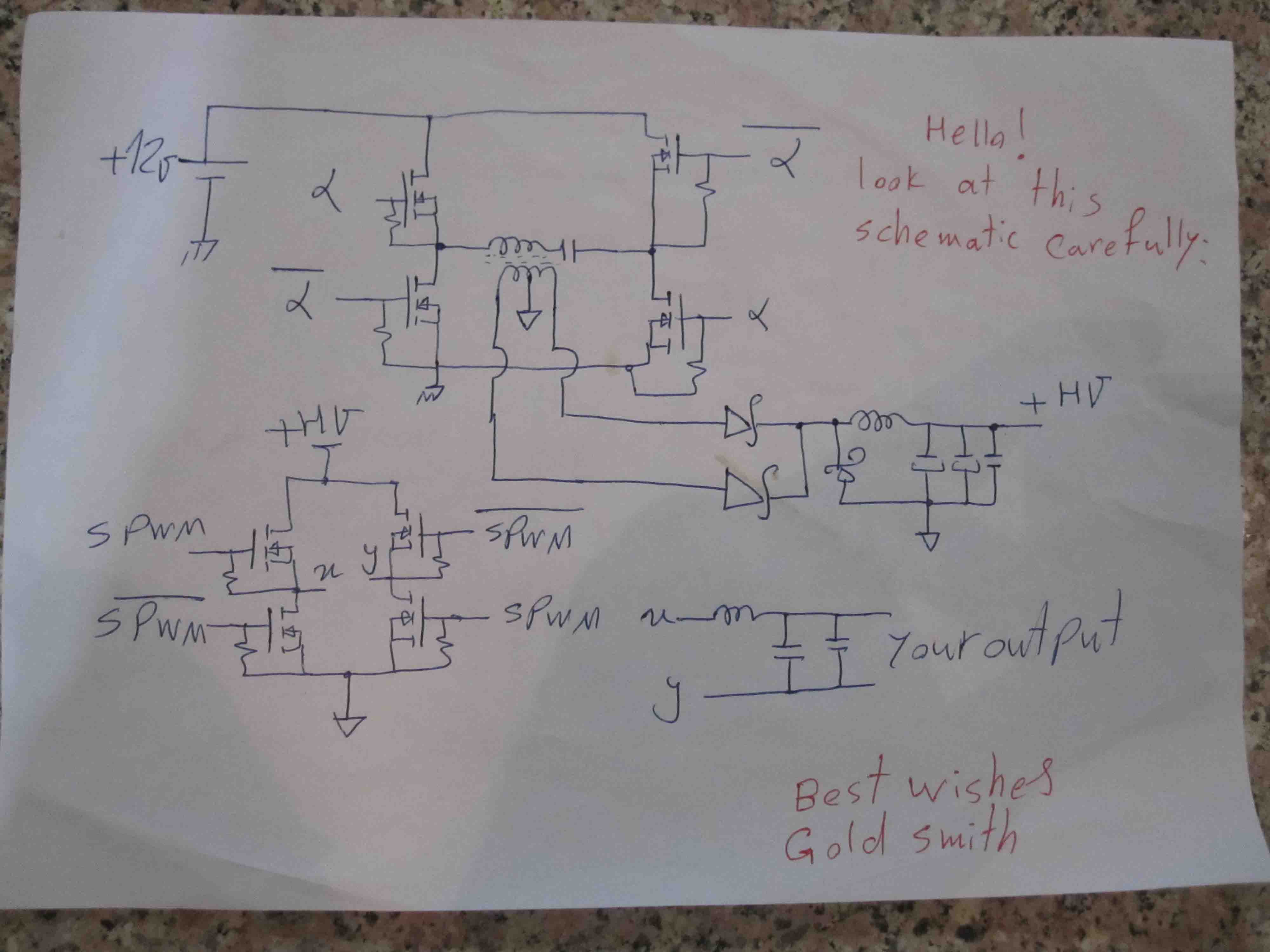
I seek your help to design a 400w highly efficient switched mode power supply to high voltage dc equipment in cars, say 100v.

kindly help especially with topology choice.


Kind Regards.
 

Dear Phyllis
Hi
Just this ? 12 volts to 100 volt converter ? it is easy , try to use a simple boost converter ! or if isolation is important to you , use a forward or push pull converter which are suitable for your purpose .
Best Wishes
Goldsmith
 

pls i need a schematic diagram 4 dis but @ 230volt
 

Hi,
Thank you for your help. How do I get a circuit diagram/schematic of the same. Push pull topology.

Kind Regards.
 

4 inverter using switcìng mode.1000watts
 

Dear mossses
Hi
More informations needed to give best help . such as : 1- How much will be the frequency of out put ?
and ow much is your input current ? and ... etc
Best Lucks
Goldsmith
 

50 hz .current at least 120amp
 

But you didn't tell , what kind of wave form do you need exactly and what can be your input current ?
It is simple , you'll have many many ways , but SPWM and link inverter is suitable . and you can design it simply . ( at first , you'll design a simple H bridge to earn higher voltage from your lower voltage but with an HF transformer and without SPWM and without any feed back . and then a simple H bridge with SPWM and without any transformer .
Best Wishes
Goldsmith
 

modified sine wave will do.input current of 125 amp using 12volt.
 

Humm ! no problem , you can do it , simply . ( i think your input is gang of batteries . at first you should create an square wave with the frequency about 200 KHZ and then create dead time ( you should has A and A' that these signals has enough dead time ) and then building an H bridge with an HF transformer to achieve higher voltage .
So , at first let me ask you , are you familiar with ferrite transformer calculations ? if no , no problem i'll guide you .
And about another sections of this project , let me talk about that after you built this section ( this section don't need feed back because of stable voltage of battery ) and the out put of that HF transformer should rectify and then filter !
Best Wishes
Goldsmith
 

i'll really appreciate a schematic diagram of it cos am stil a novice
 

Humm ! hi to both of you , my friends !
Phyllis Mathenge
Where is your problem , right now ?
mossses
I'll draw it's schematic for you .
Best Wishes
Goldsmith
 

Hi Phyllis
ic. Kindly assist.
What do you mean by that ?
I think you're referring to the SG3526N . well , where in the schematic is your problem ? selecting the frequency of PWM ? selecting the value of dead time ? selecting the proper value for compensation network ?
Tell me a bit more about your problem , exactly , thus i can help you correctly .
Best Wishes
Goldsmith
 

Dear mossses
Hi
sorry , i forgot it , today i'll attach a diagram.
Best Regards
Goldsmith
 

Dear Dear mossses
Hi again
See , below , please :


Try to think about it , if you can't understand it , don't worry , i'll describe it in detail .
Good luck
Goldsmith
 

Status
Not open for further replies.

Similar threads

Part and Inventory Search

Welcome to EDABoard.com

Sponsor

Back
Top