Continue to Site

Welcome to EDAboard.com

Welcome to our site! EDAboard.com is an international Electronics Discussion Forum focused on EDA software, circuits, schematics, books, theory, papers, asic, pld, 8051, DSP, Network, RF, Analog Design, PCB, Service Manuals... and a whole lot more! To participate you need to register. Registration is free. Click here to register now.

single phase inverter using two npn transistors

Status
Not open for further replies.

nxt_

Member level 4
Joined
Aug 16, 2010
Messages
69
Helped
4
Reputation
8
Reaction score
4
Trophy points
1,288
Location
Egypt
Activity points
1,834
dear all,
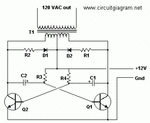
greetings, could anyone tell me how this is circuit works? and what i need to do in order to make it works for 220v/50hz output
i will use it to control 75 watt ac motor.
thanks

NOTE: THE component mentioned below are for 120v/60 output.

Components list:

Part Total Qty. Description Substitutions
C1, C2 2 68 uf, 25 V Tantalum Capacitor
R1, R2 2 10 Ohm, 5 Watt Resistor
R3, R4 2 180 Ohm, 1 Watt Resistor
D1, D2 2 HEP 154 Silicon Diode
Q1, Q2 2 2N3055 NPN Transistor (see “Notes”)
T1 1 24V, Center Tapped Transformer (see “Notes”)
MISC 1 Wire, Case, Receptical (For Output)
 

Attachments

  • viu1237425056g.gif
    viu1237425056g.gif
    9.3 KB · Views: 104

You have better inverter circuit on edaboard just search. This circuit is simple multivibrator to give life to square sine.

This circuit cant handle your needs make some better circuit. Calc inrush current of motor at start.
 
  • Like
Reactions: nxt_

    nxt_

    Points: 2
    Helpful Answer Positive Rating
I have used this circuit to get the HV required for a capacitive discharge elctronic ignition for a car. The novel thing about it is that it is "bomb" proof, a short circuit on its output causes the circuit to oscillate at a very much higher frequency(50 KHZ) depending on the leakage inductance of the transformer.
Frank
 
  • Like
Reactions: nxt_

    nxt_

    Points: 2
    Helpful Answer Positive Rating
The circuit is simple, but according to 2N3055 guaranteed data doesn't necesserally work up to 75 W.

In the present version, I don't like, that Vbe is possibly driven into reverse zener breakdown, causing degradation of transistor performance. Tantalum capacitors aren't particularly suited for pulse currents, early failure may be a result. Empirical circuit improvements are surely possible, but better with solder iron and oscilloscope rather than pencil and paper.
 
  • Like
Reactions: nxt_

    nxt_

    Points: 2
    Helpful Answer Positive Rating
GOOD i need 75watt inverter for Sewing machine. the i/p dc voltage is 12Volt car battery, 3 days ago i made full bridge single phase inverter with four IGBT and pic18f452,4n35 as optocoupler, i only know this part, but the part of filtering and converting it to a good sine wave i am very confused in it. inaddition i need to know the relation between the load (inductive or resistive) and the (switching frequency,duty).

thanks.

You can search edaboard threads there is many threads about that, also You will find and circuits.

For first aid see this material :
 

Attachments

  • 1328052979319-uploadscreenshot-dot-com.png
    1328052979319-uploadscreenshot-dot-com.png
    287.7 KB · Views: 82
  • an9611.pdf
    335 KB · Views: 88
  • MQP_D_1_2.pdf
    5.3 MB · Views: 87
Last edited:

Status
Not open for further replies.

Similar threads

Part and Inventory Search

Welcome to EDABoard.com

Sponsor

Back
Top