Continue to Site

Welcome to EDAboard.com

Welcome to our site! EDAboard.com is an international Electronics Discussion Forum focused on EDA software, circuits, schematics, books, theory, papers, asic, pld, 8051, DSP, Network, RF, Analog Design, PCB, Service Manuals... and a whole lot more! To participate you need to register. Registration is free. Click here to register now.

[SOLVED] 29 second shot clock using 74192 & 555 circuit diagram

Status
Not open for further replies.

arwayeyen

Junior Member level 3
Joined
Feb 27, 2012
Messages
31
Helped
0
Reputation
0
Reaction score
0
Trophy points
1,286
Activity points
1,484
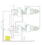
Hi. Could anyone please help me with this. I'm trying to design a 29 second shot clock or basically a countdown circuit using 74LS192 & NE555 Timer. If anyone could please help me out with a proper diagram for this, it will be a huge help for me to pass my practical exam. Thank you. :grin:
 

Thank you. So how do I set it to 29 seconds? And if you could please provide the full parts list for this, that would be great.

---------- Post added at 07:54 ---------- Previous post was at 06:58 ----------

oh and what kind of switch is this?


Oh and can I use a TIP102 transistor instead of the one stated? Thanks
 

Update: So I have placed everything and I used a TIP102 Transistor which is also a Darlington type instead of the BCX38B. One problem I couldn't solve is the Load. It wouldn't load up 24 on the 7 segment. The LED near the transistor lights up as well as the other one blinking. What could be wrong? Thanks.

---------- Post added at 16:54 ---------- Previous post was at 16:40 ----------

now it's counting down by 10s

---------- Post added at 17:05 ---------- Previous post was at 16:54 ----------

update: now it's counting from 24 to 0 but in different display. From 42,32,22,12. Backwards.

---------- Post added at 17:12 ---------- Previous post was at 17:05 ----------

Last update: I have now made it to 24 seconds. Now how do I set this to 29?

---------- Post added at 17:35 ---------- Previous post was at 17:12 ----------

FINAL UPDATE: Finally got it to work to 29! You the boss, man! THANK YOU SO MUCH!
 

I’m glad you have managed yourself to discover how to change from 24 to 29 seconds. In order to do this we need to change the units counter parallel load, now load 9 = ‘1001’ instead 4 =’0010’. :cool:
 

Attachments

  • 29 seconds clock.GIF
    29 seconds clock.GIF
    110.2 KB · Views: 234
  • 29 seconds counter diagram.JPG
    29 seconds counter diagram.JPG
    214.6 KB · Views: 113
Last edited:

Yes. I got it. Although what is the function of the potentiometer? I can't seem to get a consistent 00 on the display whenever I connect it to the supply but when load is pressed, the count down begins.
 

can anyone provide me with the simulation program already ? been doing this for 2 days and cant get it right. im using livewire as the simulation and i badly need this one.
 

Actually it’s more complicated to simulate this circuit. :grin:
For that design I have used also some analog elements in order to minimize the number of digital logical circuits in use. You may try to simulate the modified circuit, not including 1Hz clock generator and external Clear/Load signals. (see the attached diagram).
 

Attachments

  • Simulation.png
    Simulation.png
    108.8 KB · Views: 141

thanks for replying. but i think i needed the three switches (reset, pause, play). and also is U14 supposed to be the 555 ? thanks in advance :)
 

Re: 29 second shot clock using 74192 & 555 circuit diagram

In the last diagram the U14 it’s a 4 bit data generator used to replace the push buttons and the clock generator. For your simulation you may use the necessary switches and a dedicated 1Hz clock generator to replace the U14 circuit.
 

Status
Not open for further replies.

Similar threads

Part and Inventory Search

Welcome to EDABoard.com

Sponsor

Back
Top