Continue to Site

Welcome to EDAboard.com

Welcome to our site! EDAboard.com is an international Electronics Discussion Forum focused on EDA software, circuits, schematics, books, theory, papers, asic, pld, 8051, DSP, Network, RF, Analog Design, PCB, Service Manuals... and a whole lot more! To participate you need to register. Registration is free. Click here to register now.

Adjust signal (timer)

Status
Not open for further replies.

Yoshidk

Newbie level 6
Joined
Oct 27, 2011
Messages
14
Helped
0
Reputation
0
Reaction score
0
Trophy points
1,281
Activity points
1,393
Adjust signal (monostable 555 timer)

Hello everyone

Im building a clapswitch, and i have most of it working
The schematic is here:
Sensitive-Clap-Switch-550x280 - Kopi.png

My problem is after the first op amp, a clap will produce several pulses, and the counter will count all of them, so i need some way to turn these signals into one
My first thought was a Monostable 555 timer, and i found this schematic (R=80 kohm, C=0,1 uF = 0,088 sec)
220px-555_Monostable.svg.png


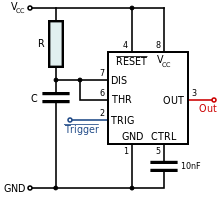
(I used "out" on the first schematic to "Trigger", and "Output" to "In" on the first schematic)

But i cant get any output on the 555 timer, what am i doing wrong?

Also, is there an easier way to solve my problem?

Thank you
Jeppe Clausen
 

Dear Yoshidk
Hi
Can you tell me a bit more , explanations, about the aim of your circuit , please? for example why you used that microphone ? and what will do that , at your timer ? Thus , probably , i can help you .
Best Wishes
Goldsmith
 
Last edited:

Yea ofc
The purpose of the circuit is, sharp noises (like when you clap your hands), will make a 230V relay open or close. Then this relay can controll ie the bedroom lights..

The purpose of my problem (the timer) i can explain with a paint illutration:

The first graph shows the voltage of the output of IC1 when a clap is sound.. There is both clap and some random eccos
The second graps shows what i want on input 14 at IC2, the important thing is the voltage only "rise" once
paint1.png

So bascily i want to eliminate the output caused by the ecco when a clap is sound..
I believe a timer would set IC1 output high at the desired time (88ms), so no matter how much ecco is made, the signal will only have one "voltage rise", and IC2 will count only one

I hope this explains it better

Thank you
 

Re: Adjust signal (monostable 555 timer)

I used "out" on the first schematic to "Trigger", and "Output" to "In" on the first schematic
That, surely, is your problem.

The output of IC1, which you have labelled "In", should trigger the 555, and the output of the 555 should go to the 4017's clock, pin 14, which you have labelled "Out".
 

Ah yea, i wrote this wrong, i send the signal from the first part into Trigger, and Output from 555 to next part
 

Status
Not open for further replies.

Similar threads

Part and Inventory Search

Welcome to EDABoard.com

Sponsor

Back
Top