Continue to Site

Welcome to EDAboard.com

Welcome to our site! EDAboard.com is an international Electronics Discussion Forum focused on EDA software, circuits, schematics, books, theory, papers, asic, pld, 8051, DSP, Network, RF, Analog Design, PCB, Service Manuals... and a whole lot more! To participate you need to register. Registration is free. Click here to register now.

2 digit 7 segment display counter

Status
Not open for further replies.

useless018

Junior Member level 1
Joined
Feb 10, 2012
Messages
16
Helped
6
Reputation
12
Reaction score
6
Trophy points
1,283
Activity points
1,371
hello to everyone,,,

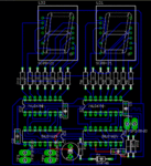
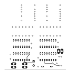
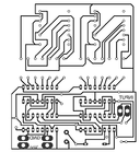
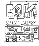
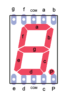
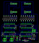
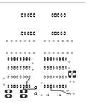
i have a problem in designing the pcb layout of a 2 digit 7segment display counter using 74LS47 and 74LS192 IC's,,,,,,
can anyone help in designing it's pcb layout,,,,,,,
thank you very much ^_^
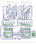
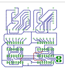
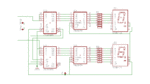
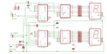
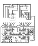
 

@useless018
First you need to decide what type of 7 segments LEDs display available for the project: two pieces single digit or one piece double digit. Later check LEDs displays pinout in the datasheet. :grin:
 

One example of the PCB:
 

Attachments

  • PCB test1.GIF
    PCB test1.GIF
    106.7 KB · Views: 146
  • PCB test 2.GIF
    PCB test 2.GIF
    70.3 KB · Views: 102
:) ...the schematics for the PCB:
 

Attachments

  • Counter test.GIF
    Counter test.GIF
    15.2 KB · Views: 111
Maybe we need to improve the actual diagram. :)
We may add some decoupling capacitors, automatically reset at POWER ON and jumpers to connect external RESET button.
. See the new version here:
 

Attachments

  • counter v3all.GIF
    counter v3all.GIF
    69.6 KB · Views: 120
  • Counter v3t.GIF
    Counter v3t.GIF
    28.6 KB · Views: 100
  • Counter v3x.GIF
    Counter v3x.GIF
    69.2 KB · Views: 90
  • Counter v3a.GIF
    Counter v3a.GIF
    69.2 KB · Views: 102
  • counter_v3 sch.GIF
    counter_v3 sch.GIF
    24.4 KB · Views: 108
thank you mister rf ,,,
the 7 segment display that im going to use is 2 pieces of one digit 7 seg.display common anode,,,
and its pin configuration looks like this,,,
22_1329050072.png
 

OK. :grin: The new PCB:
 

Attachments

  • C_all.GIF
    C_all.GIF
    66.1 KB · Views: 102
  • C_Top.GIF
    C_Top.GIF
    30.6 KB · Views: 94
  • C_Bottom.GIF
    C_Bottom.GIF
    76.1 KB · Views: 101
thank you very much mister_rf your pcb layout have help me alot ^_^,,,,,,

---------- Post added at 14:31 ---------- Previous post was at 13:31 ----------

thank you very much mister_rf,,,,, but my professor have instructed us to have a four input i dont remember it but as far as i remembered it is for the carry, borrow and reset i forgot the other one,, but i will ask him tommorow,,,,, so there will be some modifications in the pcb layout that you gave me,,,,,, thank you very much for the help,,, so by tommorow i will clearly tell all the specification that my professor gave me,,, thank you very much again mister_rf,,,,,,
 

Status
Not open for further replies.

Part and Inventory Search

Welcome to EDABoard.com

Sponsor

Back
Top