m.kelley
Newbie level 4
- Joined
- Jan 29, 2012
- Messages
- 7
- Helped
- 0
- Reputation
- 0
- Reaction score
- 0
- Trophy points
- 1,281
- Location
- Texas - for now
- Activity points
- 1,333
Hello,
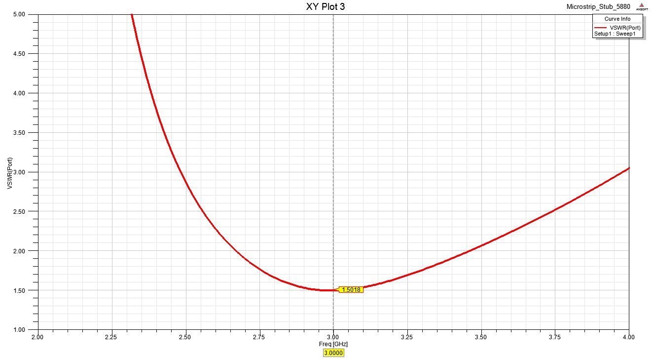
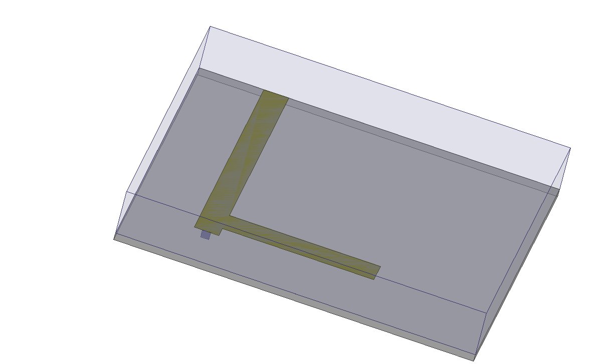
I am currently building a demo of a microstrip line with a tuning stub. The transmission line is terminated in a load impedance of 100-50j ohms. The microstrip line has a Z0 of 50 ohms, and the stub has a Z0 of 100 ohms. I know my designs for the microstrip lines work, but I am having trouble terminating the transmission line with the fixed load. I have designed the stub length and distance from the load with a smith chart, but the magnitude of my S11 parameter is about 0.54. I think my main problem is how I am simulating the load. Oh, and I'm also feeding the structure with a waveport at one end. I have used two geometries for the load. One was to assign one outer face of the model, both the air and substrate, as an impedance boundary. The other design was to have a square going down into the substrate, and assign it as an impedance boundary. For this last design I made the air box and substrate longer than the transmission line - the impedance boundary was not touching the outer boundary of the model. In both cases my network was not matched. In short, hod do you simulate a fixed general load impedance in HFSS?
Michael Kelley