kasuncharya
Newbie level 5
- Joined
- Jan 25, 2012
- Messages
- 9
- Helped
- 1
- Reputation
- 2
- Reaction score
- 1
- Trophy points
- 1,283
- Location
- Pannala,Sri Lanka
- Activity points
- 1,342
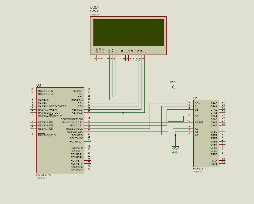
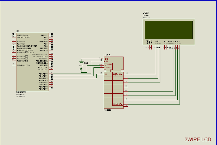
I want to drive 7 stepper motors, dual line 16 char LCD module and a single port for Inputs.
I am using 16F877A .
How can I have that much of I/O pins by cascading or synchronizing or any other method using multiple 16F877A chips.
I am using MikroC for development.
I am using 16F877A .
How can I have that much of I/O pins by cascading or synchronizing or any other method using multiple 16F877A chips.
I am using MikroC for development.