Continue to Site

Welcome to EDAboard.com

Welcome to our site! EDAboard.com is an international Electronics Discussion Forum focused on EDA software, circuits, schematics, books, theory, papers, asic, pld, 8051, DSP, Network, RF, Analog Design, PCB, Service Manuals... and a whole lot more! To participate you need to register. Registration is free. Click here to register now.

Buck Convertor problem

Status
Not open for further replies.

zami123

Junior Member level 1
Joined
Jan 2, 2012
Messages
15
Helped
0
Reputation
0
Reaction score
0
Trophy points
1,281
Activity points
1,400
Buck Convertor using IR2103 problems

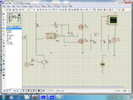
Hi everyone,i have almost read all the posts realting to the buck convertor but havent got any solution to my problem.I am using IGBT mg300H1UL1 in the convertor.The gate of Igbt is connected to ATmega 16 from which i am generating pwm. I am using IGBT driver Ir2103.But problem is that whenever i put IGBT 300H1U1,the i.c blown.I have made the design of i.c on proteus with mosfets 840 and everything is working fine but replacing with mg300H1Ul1 ,the i.c blow..Any one kindly help me with the problem...????
 

Attachments

  • BUCK igbt.png
    BUCK igbt.png
    172.3 KB · Views: 151

Which IC blows? If one of the IGBTs is blowing then it might be a cross conduction issue.

Also you show that you're doing synchronous rectification with IGBTs, but there's no point in that from an efficiency perspective. Only mosfets really make synchronous rectification worthwhile... So I would try removing the lower IGBT (but keep the catch diode D2) and see if that solves the problem.
 
The IGBT driver circuit you are using is clearly not appropriate for driving the IGBT you mentioned for the following reasons:
- The IGBT needs much more current to switch than the specified by the driver (130 mA nominal is too low, you nead some Amps). You may be buring the driver due to overcurrent at the output (which could be limited with gate resistor, but would lead to very slow switching times).
- Its specified voltage ranges are too narrow for driving a high voltage and current IGBT. These IGBT have high parasitic capacitances. Whenever a transient voltage appears, it is transferred to the driver directly and it burns due to overvoltage.
- There is a lack of gate protections (zener, pulldown gate resistor) to limit these transients.
- Have you checked that all the gate drive paths have small parasitic inductances (as short as possible and without vias or long cables)
You should use a more specific gate driver (with higher current capacity) as well as improving the schematic with extra protections.
Check the following documents:
http://www.ixysrf.com/pdf/switch_mode/appnotes/5mosfet_driver_theory_and_applications.pdf
http://www.irf.com/technical-info/designtp/dt04-4.pdf
Good luck!

Ernest
 
Hello my friend!
Your circuit has many problem.
1st: you can not use a simple bjt and resistor as a not gate .
2nd: when you want use a mosfet as a diode , you should create the dead time at your PWM.
3rd:if you used Q2 , it is not necessary to use D2 .
Best Wishes
Goldsmith
 
. Only mosfets really make synchronous rectification worthwhile... So I would try removing the lower IGBT (but keep the catch diode D2) and see if that solves the problem.
Thnks a lot for the reply..Yup i tried removing the lower mosfet n just usng one high side of ic with the IGBT.but it blew.
And ic is IR2101...
I am basically designing a circuit so that by changing pwm,my voltage changes.

---------- Post added at 11:48 ---------- Previous post was at 11:29 ----------

---------- Post added at 11:52 ---------- Previous post was at 11:48 ----------

.
- There is a lack of gate protections (zener, pulldown gate resistor) to limit these transients.

Good luck!

Ernest
Can u pls suggest me the driver and gate protection circuit..??????
I am actually building a circuit which voltage can be changed by changing the pwm of ATmega16....

---------- Post added at 12:05 ---------- Previous post was at 11:52 ----------

And will it effect if i common the grounds of power suply of i.c and IGBT????
 

If you want to work with IRF, you could try IR21141. The datasheet (**broken link removed**) includes schematic and layout good practices (crucial if you want to reduce bad behavior of the circuit).
Place a 15 V TVS between gate and emiter as well as a 3.3 kOhm resistor to ensure turn off and protection against transients.

---------- Post added at 16:10 ---------- Previous post was at 16:09 ----------

The IC includes a desaturation protection, quite recommended when working with IGBTs since they can fail "easily" at shortcircuit.
 

Thanx a Lot sir 4 replying....cn u tell me please dat wat is TVS??? its T.v protection diode,if m not wrong????
And we have to place resistor betweeen gate and emitter???
 

A TVS is a Transient Voltage Suppressor. There are many kinds, typically it works like a "Zener", clamping overvoltages that appear at the gate, but is more robust than a Zener and withstands higher current pulses.
The 3.3 kOhm is placed to ensure safe turn off of the IGBT and to avoid unwanted turn-on due to the capacitive coupling between gate, collector and emitter (fast dv/dt could actually cause unwanted IGBT turn on!)
By the way, which PWM frequency are you using?
 
Thnks a lot for the reply..Yup i tried removing the lower mosfet n just usng one high side of ic with the IGBT.but it blew.
And ic is IR2101...
I am basically designing a circuit so that by changing pwm,my voltage changes.

When the failure happens, does it happen immediately after startup, or does it take a while? Do any components heat up beforehand? Are you doing the test with a load?

Also, you don't show a bypass capacitor on the DC input to the buck converter (or the IR2101). Having a good, high frequency cap on the input is important to prevent overvoltage transients on the collector of the IGBT.

In situations where you're getting failures without apparent cause, I highly recommend doing single pulse testing. This is where instead of driving the circuit continuously with a PWM waveform. You just put in very short (like a few microseconds to start), single pulses (maybe at a frequency of 1Hz) and watch the transient behavior of the circuit. Watch the rise and fall times on the gate/source, watch the capacitor bootstrap voltage, watch the inductor current, etc. This testing method allows you to make careful measurements without risking a failure. If everything looks okay, you can gradually make the pulses longer, or increase their frequency, and watch if anything changes. Eventually you should be able to identify the problem.

I recommend doing pulse testing with an actual pulse generator, as opposed to a MCU (makes things a lot simpler). If you post the results of the pulse test then I bet we'll solve the problem.
 

By the way, which PWM frequency are you using?
Thanks sir....I am generating PWM at 4 khz. SO,i have to change my i.c first or i should experiment with the older IR2101 along with the modifications u told???
 

I am generating PWM at 4 khz. SO,i have to change my i.c first or i should experiment with the older IR2101 along with the modifications u told???

Change to the new IC or a similar one. The IGBT you are using requires a higher current driver if you want to switch it at reasonable speed and reduce switching loses. With the 100 mA gate drive and the gate charge of your IGBT it will be a way too slow and you should expect long tail currents at turn off and power loses.
In addition, I would recommend using the desaturation protection with this kind of "expensive" power switches.

Ernest
 

Status
Not open for further replies.

Similar threads

Part and Inventory Search

Welcome to EDABoard.com

Sponsor

Back
Top