Continue to Site

Welcome to EDAboard.com

Welcome to our site! EDAboard.com is an international Electronics Discussion Forum focused on EDA software, circuits, schematics, books, theory, papers, asic, pld, 8051, DSP, Network, RF, Analog Design, PCB, Service Manuals... and a whole lot more! To participate you need to register. Registration is free. Click here to register now.

Drain source osillations of mosfet in pwm inverter

Status
Not open for further replies.

sabu31

Advanced Member level 1
Joined
Jan 28, 2011
Messages
446
Helped
12
Reputation
24
Reaction score
13
Trophy points
1,298
Activity points
5,153
Hi
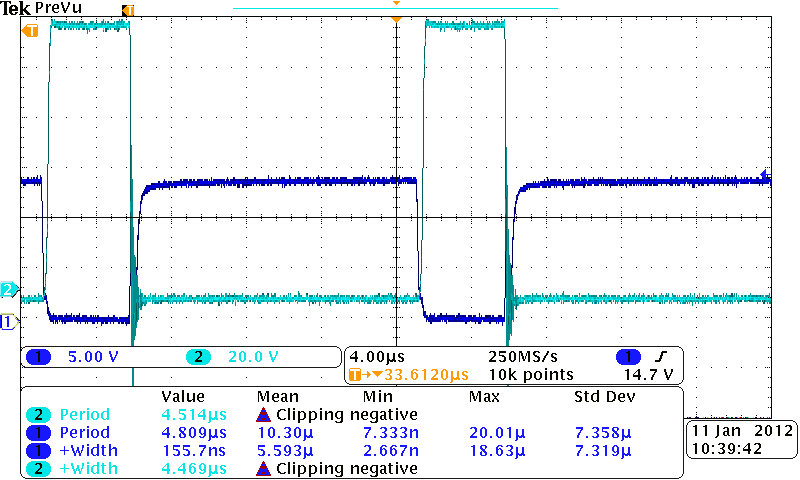
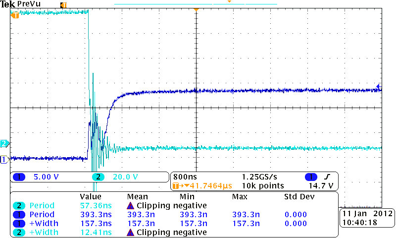
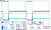
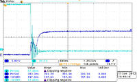
I am driving mosfets of single phase pwm inverter using ir2110, the switching frequency is 50Khz, mosfet is IRFPE50PBF. There are oscillations at turn on instant. I have attached the waveforms[drain-source, gate-source] of the lower switch of 1st leg of the inverter.Even though its not causing much of heating, i would like to eliminate it as much as possible.Please give me reason for this oscillations. Thanking you.
 

One likely cause is that the impedance of the gate driver is too high, which can cause parasitic turn on/turn off of devices during switching transients. Are you using a gate resistor or RD network?

When observing these things, you should make sure you're taking measurements carefully. If possible look the the Vgs of both FETs in the leg at the same time, using isolated/differential probes. That can make things much more obvious.
 
  • Like
Reactions: sabu31

    sabu31

    Points: 2
    Helpful Answer Positive Rating
... or your gate resistor could be too low. If you are going to put a resistor in series make sure it is no more than 10 Ohms. You want good gate drive, but sometimes the 10 Ohms will dampen any such oscillations
 

It might just be ringing, the "tank" is your wire harness (L)
and the FET+PCB capacitances. Or the ringing might be
in the ground loop. I've seen that simply adding the probe
capacitance to the output switching node can increase
the ringing markedly; try a series 1K resistor between the
node and the probe tip, this would make about a 100MHz
pole which should still pass that ring-note if it's sourced
elsewhere.
 
  • Like
Reactions: sabu31

    sabu31

    Points: 2
    Helpful Answer Positive Rating
I am using 10 ohms for turn on and 5 ohms(one is bypassed by diode) for turn off.

---------- Post added at 15:17 ---------- Previous post was at 15:14 ----------

yeah, dick_freebird,..I am also doubting whether its due to probe ..Ground loop is unlikely as i have made ground trace as wide as possible..
 

Do not discount any ground loop - even the area enclosed by
your probe and its ground-clip can pick up magnetic induction
when you're talking tens of amps and kV/uS slew rates.
 

... or your gate resistor could be too low. If you are going to put a resistor in series make sure it is no more than 10 Ohms. You want good gate drive, but sometimes the 10 Ohms will dampen any such oscillations
It's true that having a larger Rg can dampen transients by slowing the switching action, but this that's not the proper way to deal with the transients, since the slower switching degrades efficiency. The primary function of a gate resistor should be to dampen ringing on the gate (caused by stray inductance on the gate driver current loop), not to dampen ringing on Vds. That should be dealt with by using proper layout techniques, and snubber networks.

Unless he has a large amount of stray inductance on his gate leads, I doubt, 5/10 ohms is not enough to dampen it.

I am using 10 ohms for turn on and 5 ohms(one is bypassed by diode) for turn off.
Okay, let's do some calculations. The Cgd of your FET is given as 490pF in the datasheet. From your waveforms, it looks like you have a Vds of 100V and a fall time around 100ns. So you have current flowing into your gate resistor equal to i=490pF * 100V/100ns, or 0.49A. That will induce 4.9V across your 10 ohm gate resistor. Also there will be a bit more than that, due to resistance in the gate driver IC and the FET itself, along with stray inductance. So during "turn on" you're losing 5V on your gate drive voltage, which may be enough to cause parasitic turn off. And a similar thing will happen on the upper FET in the leg possibly leading to parasitic turn-on at the same time. The two can work together to create nasty oscillations.

I would try decreasing the gate resistors, by half. If your gate driver circuit layout is good, you shouldn't need more than an ohm or two anyways to damped out ringing on the gate.

---------- Post added at 15:17 ---------- Previous post was at 15:14 ----------

yeah, dick_freebird,..I am also doubting whether its due to probe ..Ground loop is unlikely as i have made ground trace as wide as possible..
The importance of proper ground referencing can't be overstated enough. Just a few tens of nanohenries in the switching path can cause gross waveforms to appear. You should put the ground clip directly on the source terminal of the FET, and the probe tip directly on the gate terminal. Make sure to be cautious when using non isolated probes. Is your inverter isolated?
 
Last edited:
  • Like
Reactions: sabu31

    sabu31

    Points: 2
    Helpful Answer Positive Rating
Dear sabu
Hi
It is usual . you can improve it with a simple snubber network.
Bes Wishes
Goldsmith
 

Dear sabu
Hi
It is usual . you can improve it with a simple snubber network.
Bes Wishes
Goldsmith
No, that level of ringing on Vgs is not normal, and needs to be fixed. Vgs should have practically no ringing, and absolutely none near the threshold voltage of the FET.
 

And about it's reason : what kind of inverter , you have designed? and do you have an inductor in it's out put?
If yes, i should say an important thing , that i have seen some engineers didn't pay attention to that : the inductor has some parasitic capacitor , and you should design and wind your inductor carefully . ( your inductor generated some parasitic capacitor , and the capacitors , created resonant frequency , with your inductor , and thus you can see those over shoots.)

---------- Post added at 19:54 ---------- Previous post was at 19:53 ----------

Dear Friends
For optimizing , that effect ,you can use a series ferrite bead with the gate ( a little inductance , can help to preventing the VGS from that oscillations)
Best Wishes
Goldsmith

---------- Post added at 19:58 ---------- Previous post was at 19:54 ----------

By the way , that over shoots are not pretty important at this application.
 

Status
Not open for further replies.

Part and Inventory Search

Welcome to EDABoard.com

Sponsor

Back
Top