Continue to Site

Welcome to EDAboard.com

Welcome to our site! EDAboard.com is an international Electronics Discussion Forum focused on EDA software, circuits, schematics, books, theory, papers, asic, pld, 8051, DSP, Network, RF, Analog Design, PCB, Service Manuals... and a whole lot more! To participate you need to register. Registration is free. Click here to register now.

Help me debug my PICKIT2 clone....

Status
Not open for further replies.

annna

Member level 2
Joined
Jun 17, 2010
Messages
52
Helped
1
Reputation
2
Reaction score
1
Trophy points
1,288
Location
pak
Activity points
1,682
Hi..
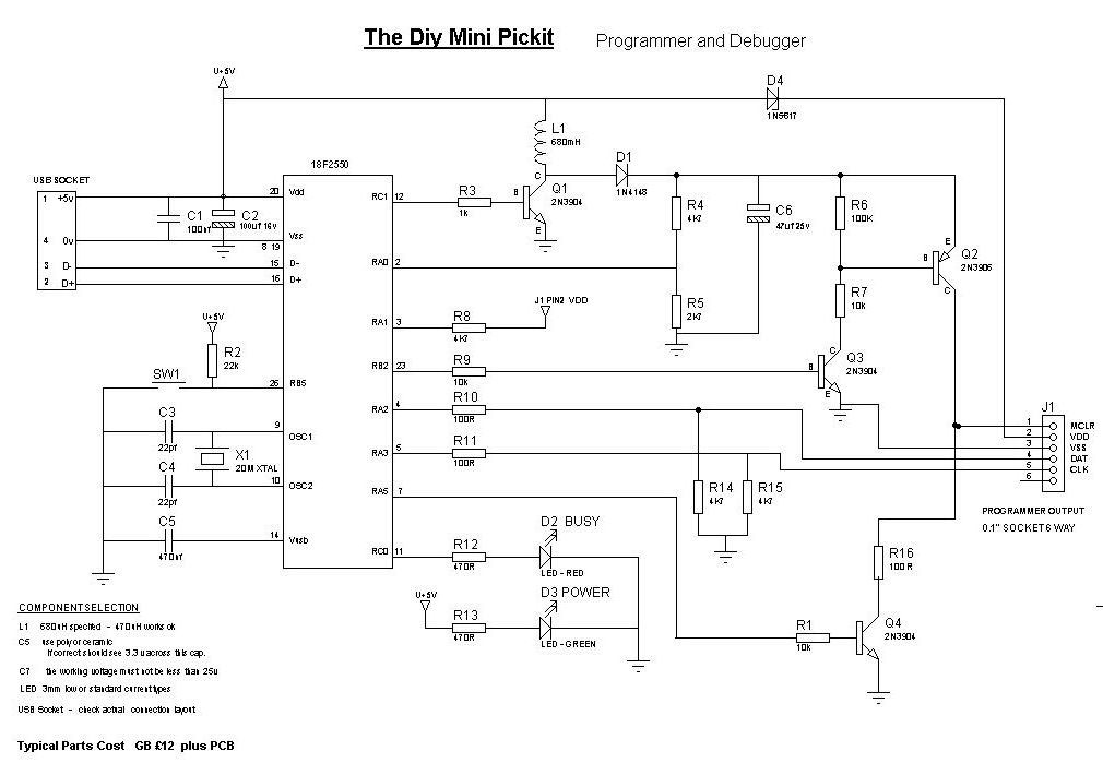
I made a PicKit2 clone based on the following schematic...


When I connect this circuit to my PC and open MPLAB to connect PICKIt2 I see that the busy LED keeps on blinking and MPLAB keeps on loading... even if I wait for hours nothing happens until I disconnect PicKit2.... On disconnecting I receive this error..

Initializing PICkit 2 version 0.0.3.63
Found PICkit 2 - Operating System Version 2.32.0
Target power detected ( 4.39V)
PK2Error0008: Read failure (GetLastError = Overlapped I/O operation is in progress.)
PICkit 2 Ready

Can anyone suggest what is the problem...
 

Hi,

Below is a corrected diagram, the difference is on the USB socket, pin 2 and pin 3 connections are reversed.
 

Attachments

  • minipk2.jpg
    minipk2.jpg
    66.6 KB · Views: 160

yes i forgot to mention I used the correct pinout for that USB connector... Still I am having this problem....
 

Hi,

3 questions, are you using a Laptop or Desktop ?

What voltage do you measure across the 4550 pins 19 and 20 ?

Do you have anything connected to the Pk2 outputs , a pic chip or a full circuit ?

Download from Microchip the Pickit2 program V2.61, that is a stand alone programmer and has lots of testing tools.

Connect using that and see what error it gives .
 

Hi,

voltage across 2550's pins 19 20 is 5.00 volts........

I have only a pic chip connected to its outputs...

While using Pickit2 V2.61 same behaviour was observed... when I go Tools> Check Communication... It keeps on loading and nothing happens until I disconnect Pickit2...

Help me out.....
 

please test the programmer without connecting a PIC at its output, first set the Vpp to 12V or so, then try placing a pic for necessary programming.
change the C2 to 10uF and R10 and R11 to 47 ohms and then try gain. if necessary re load the firmware. perhaps some corruption might have happened.
 
Last edited:

Same results.... No change.... I'm frustrated now..
 

this is the moment one has to learn. if everything what we make works just, there is no learning

You might have made some mistake. Please take a close up well focused photo during sunlight of the pcb you assembled, upload so that we can try to check it. preferably both the sides.
 
Last edited:

Double check your connections and check the microchip pickit 2 manual for how to connect icsp connector to the target.
 

Hi
Try to manage step by step
first remove devices from the PICkit2
and connect to USB
see attachmentpi.GIF
 

Hi,

As above, but if still nothing working;

Ensure MPlab is closed down.

Ensure nothing is connected to your Pk2 output socket.

Start PK2 V2.61 program.

According to your earlier posts you do get the 'Pickit2 Connected' so go to the Tools Menu and select TroubleShoot.

This allows you to check Vdd, VPP at around 12v and PGC / PGD.

Do not try and adjust anything, just see what Vdd and Vpp are reporting.

Let us know what results, if any, you get.

? Did you use any parts with different values to those shown on the circuit diagram ?

For PGD/C manually select and measure their HIGH and LOW voltages, typically 0.0V and 4.7V
 

Okay I'll try all that out and will let you guys know...
 

Oh And I have used 820uH inductor is that a problem.... Reply soon...
 

aahaa... I finally got rid of that jamming issue.... now I am able to open Pickit2 V2.61 and it shows Pickit2 found... But there is another problem now... It shows me Vpp and VDD error when I try to program.... How should I remove this bug....
 

Good. Now note the exact error and try to reproduce. as already suggested, go to trouble shooting and check the Vdd and Vpp. during that time of testing, these voltages can be measured at the respective pins at the icsp connector wrt ground. Try to record and if necessary adjust the Vpp to 11.5V at lest. then restart and check

if any issue is there still, try to lift one limb of the inductor and add a 10 ohms resistor in series. test again.
 

1. when testing Vdd it gives "An external voltage was detected on the Vdd pin at 5.0 volts" however I have no external circuit connected to its output.

2. For Vpp test the software shows 12.0volts while on ICSP conn I receive 5.0 volts...
 

neglect the first message as your circuit is permanently watching the Vdd at the pic pin thro R8, 4.7K

the measurement for Vpp shoild be done across pins 2 and 3 of the icsp and not pins 1and 3.
 

yes even for pins 2 and 3 its 5.0 volts......
 

Status
Not open for further replies.

Similar threads

Part and Inventory Search

Welcome to EDABoard.com

Sponsor

Back
Top