Continue to Site

Welcome to EDAboard.com

Welcome to our site! EDAboard.com is an international Electronics Discussion Forum focused on EDA software, circuits, schematics, books, theory, papers, asic, pld, 8051, DSP, Network, RF, Analog Design, PCB, Service Manuals... and a whole lot more! To participate you need to register. Registration is free. Click here to register now.

Will this Triac circuit work ok?

Status
Not open for further replies.

jdraughn

Junior Member level 1
Joined
Jul 29, 2009
Messages
19
Helped
0
Reputation
0
Reaction score
0
Trophy points
1,281
Activity points
1,621
I want to heat nichrome wire to build a little SMD oven and control it using a triac controlled with a microcontroller using PID.

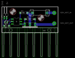
I scoured the internet looking for triac examples and they all varied. Can someone please check over my schematic and parts layout for any glaring errors?

I tested the schematic on a breadboard using a transformer that output 13v AC (400mA) that slowly warmed up my 44 ohm length of nichrome wire (after wrapping it in paper to to contain the heat since I was passing such a tiny amount of current).

It did get slightly warm after 5 minutes, and now I would like to mount the setup on a PCB, and use maybe a 60v transformer to test again before running a full 120v.

I am mostly concerned with the resistor values (they all varied on the internet), and if my board layout will work ok. Also, I don't believe I need a snubber because I am just heating nichrome wire, however I wonder if it would hurt to add one just in case the nichrome wire ends up in some kind mild coil shape which could cause inductance issues?

Thanks

TRIAC_SCHEMATIC.png
BOARD.png
 

The MOC3031M is the least sensitive of the MOC30xx series and the datasheet specifies a maximum of 15mA for guaranteed triggering whereas your circuit provides 4-5mA depending on the output resistance of your uC. But since it works with your breadboard, I guess the drive is sufficient with your sample of the device. Otherwise I don't see any "glaring error".

Regardig the snubber, I'm thinking the same way you do - not likely to be needed but it wouldn't hurt to put one in to ensure peace of mind.


Thank you for your reply, it is VERY helpful. Did you calculate the triggering voltage based on R3 (400 ohms) and 5v? I am not positive exactly what MOC I used in that schematic, but I went through my parts and I found a MOC3062 which has a maximum 10ma for guaranteed triggering. So if I use this part instead and lower the resistor value a bit, I should be good right? I would actually like it to trigger with either 3.3v or 5v, I have not decided which microcontroller I am going to use yet.

I believe I had a lower value resistor in my breadboard when I was experimenting, but the LED I had in series with my MOC was very bright. I am not sure what it's rating was so I just stuck a 390 ohm resistor in so it was easier to look at.

Also, Eagle did not have a library for my triac so I just found one with the same pinout. I am using a BTA24-600 and it says it needs a minimum 35ma trigger current. Do I calculate the triacs trigger current based on R2? I am a little confused but I think I am starting to actually understand whats happening now rather then just copying schematics off the internet. Thanks again.
 

Thank you for your reply, it is VERY helpful. Did you calculate the triggering voltage based on R3 (400 ohms) and 5v?
This is how I derived the input current to the MOC3031M:
From the datasheet of the MOC30xx triac driver, the voltage drop across the input IR LED is 1.1-1.2V. Assuming that the external LED you placed in series with MOC (LED2) is of red colour, it will take up about 1.9-2V. Assuming as a starting point that the uC has a low output resistance, then the 5V output is shared among LED2, the triac driver's internal LED and R3. The first two use up 3.0-3.2V, leaving 1.8-2.0V across R3. Divide that voltage by 400 ohms and you get 4.5-5mA. In practice, the uC output will have some internal resistance which will drop some voltage, leaving less than the full 5V available for the external circuit.

I found a MOC3062 which has a maximum 10ma for guaranteed triggering.
The MOC3062 is a zero-crossing type which means that it will trigger only when the controlled AC voltage is at or near zero. OTOH, the MOC3031 is a random-trigger type which means that it will trigger as soon as it receives an input at the LED side. Each type has applications for which it is better suited than the other. If you intend to control the temperature of the nichrome heater by varying the firing angle of the triac, the zero-crossing type is not suitable as you can trigger it only into a full cycle.

So if I use this part instead and lower the resistor value a bit, I should be good right?
As far as the triggering current is concerned, yes. But don't forget the part about random and zero-crossing.

I believe I had a lower value resistor in my breadboard when I was experimenting, but the LED I had in series with my MOC was very bright. I am not sure what it's rating was so I just stuck a 390 ohm resistor in so it was easier to look at.
If it's one of the common 3 or 5mm type, they are usually rated for a maximum of 20-30mA.

Also, Eagle did not have a library for my triac so I just found one with the same pinout. I am using a BTA24-600 and it says it needs a minimum 35ma trigger current. Do I calculate the triacs trigger current based on R2?
R2's job is to bleed off any leakage current passing from the triac's upper terminal through to its gate and prevent it from triggering itself when it should be off. The trigger current magnitude is determined by R1.

I am a little confused but I think I am starting to actually understand whats happening now rather then just copying schematics off the internet.
That's great. I've been in electronics for a long time, but there still are many things that I don't know or fully understand. The learning process is an important part of the fun.

---------- Post added at 23:04 ---------- Previous post was at 21:53 ----------

Oops! I said up there that the MOC3031M is a random-trigger type which is not correct. It's also a zero-crossing type. To use random-triggering for phase control, you can use the MOC301x or 302x series. Of these, the 3012M and 3023M are the sensitive ones. They need no more than 5mA trigger current.
 
Last edited:

Thanks again for all your help. I etched a circuit board using using a sharpy and muriatic acid/hydrogen peroxide and my board came out great. I ended up using a little heatsink from an old LM317 car adapter board I had and also attached a tiny fan to it and I while it does get pretty warm (I really need a bigger heatsink), I am able to continously run 1350 watts to my heating elements in a toaster oven.

Now the last thing really holding me up is my need for a thermocouple and a way to measure it. I do have a thermocouple from an old full size oven but it's ground based, which from what I understand makes it a little tougher to use.

I am curious as to what would happen if I used a 2.5v voltage reference with a 25/1 voltage divider so I had a .1v reference and I used that on my microcontroller as my +v reference and used ground as -V reference. Would there be too much noise?

For now I am going to use a LM335 temp sensor and limit the temp of my oven so I can work on my PID algorithms. If the temp starts to get a little hot for my sensor I can just open the door and pull it out. If I fry it then it's easily replaced.
 

Status
Not open for further replies.

Similar threads

Part and Inventory Search

Welcome to EDABoard.com

Sponsor

Back
Top