poxkix
Member level 5
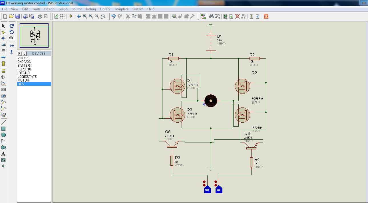
Attached image included.
Okay, I have already checked the suggested thread but didn't seem to find the exact problem with transistors.

Can anyone explain why the results are not the same? What is the requirement for a transistor to function? A voltage or current input to the base? I do not know how to read their datasheets. Can anyone help me?
Datasheets
2N1711
2N1711 datasheet pdf datenblatt - NXP Semiconductors - NPN medium power transistor ::: ALLDATASHEET :::
2N2222A
2N2222A datasheet pdf datenblatt - NXP Semiconductors - NPN switching transistors ::: ALLDATASHEET :::
Okay, I have already checked the suggested thread but didn't seem to find the exact problem with transistors.
Can anyone explain why the results are not the same? What is the requirement for a transistor to function? A voltage or current input to the base? I do not know how to read their datasheets. Can anyone help me?
Datasheets
2N1711
2N1711 datasheet pdf datenblatt - NXP Semiconductors - NPN medium power transistor ::: ALLDATASHEET :::
2N2222A
2N2222A datasheet pdf datenblatt - NXP Semiconductors - NPN switching transistors ::: ALLDATASHEET :::
Last edited: