Continue to Site

Welcome to EDAboard.com

Welcome to our site! EDAboard.com is an international Electronics Discussion Forum focused on EDA software, circuits, schematics, books, theory, papers, asic, pld, 8051, DSP, Network, RF, Analog Design, PCB, Service Manuals... and a whole lot more! To participate you need to register. Registration is free. Click here to register now.

Which type of capacitor will you choose for the output of a DC/DC converter?

Status
Not open for further replies.

powersys

Advanced Member level 1
Joined
Nov 29, 2005
Messages
439
Helped
3
Reputation
6
Reaction score
2
Trophy points
1,298
Activity points
4,981
Hi,

The datasheet of a DC/DC converter states that a output capacitor of 10uF is required for optimum performance. If we have choices (and temporarily ignore the cost factor), should I use a 35V 10uF tantalum capacitor (ESR@100kHz=0.1ohm) or 35V 10uF ceramic capacitor?

Cheers.
 

You have no choice. Ceramic capacitors are not made with such large values.
I think there is ceramic capacitor with 10uF. For example, the one quoted by Farnell as the following:

MURATA - GRM31CR6YA106KA12L - CAPACITOR, 1206, 35V, X5R, 35V, 10uF, -55°C to +85°C
£0.22

However, a tantalum capacitor with the specs below is about 5 times more expensive.

VISHAY SPRAGUE - TR3D106K035C0125 - CAPACITOR, TANTALUM, 35V, 10uF, ± 10%, 0.125ohm, -55°C to +125°C
£1.05

I wonder, apart from the ESR and operating temperature range, is there any other issues that one should consider the tantalum capacitor instead of the ceramic one?

Cheers.
 

you can use 10uF 64V ordinary electrolytic capacitor of reputed make.
He can, but if he does he will need to connect another capacitor of, say, 10nF in parallel with it.

The point of specifying a capacitor with a low equivalent series resistance is to avoid that necessity.

An ordinary electrolytic will have a relatively high value of e.s.r. and as the frequency goes up they also become inductive.
 

please post the chip name at least and / or a schematic, in and out voltages and load demand.
Otherwise we are discussing around air.

---------- Post added at 22:36 ---------- Previous post was at 22:33 ----------

@syncopator,
perfect approach, overall.
With 10uF eleco and 0.01 or 0.1 disc cap in parallel does the job reasonably well. I fear tantalum caps are many times notorious of shorting.
 

I think there is ceramic capacitor with 10uF. For example, the one quoted by Farnell as the following:

MURATA - GRM31CR6YA106KA12L - CAPACITOR, 1206, 35V, X5R, 35V, 10uF, -55°C to +85°C
£0.22
I stand corrected. Thank you.
Your good health.
 

Hi...

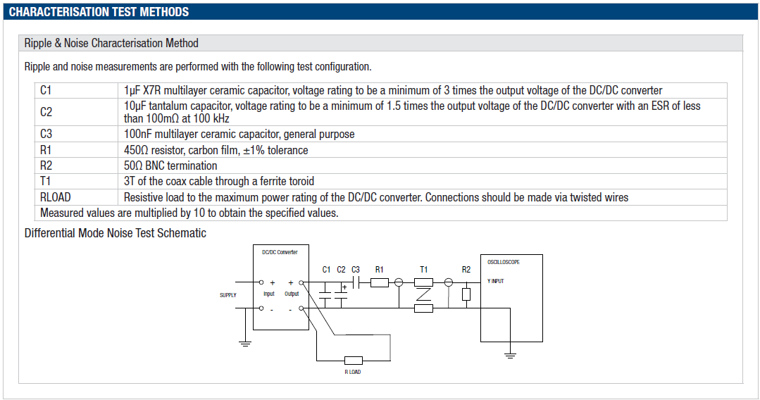
I came across the following circuit diagram which is used to characterize a DC/DC converter (NCS6S1212C). It shows that a 10uF tantalum capacitor (with ESR less than 100mOhm) is used. However, a 35V 10uF tantalum (with ESR = 125mOhm, +/-10%) in Farnell costs about $1.64, which is about five times more expensive than a 35V 10uF ceramic capacitor (X5R, +/-10%). I'm considering to use the 10uF ceramic capacitor as it's cheaper but I wonder if there is any other issue with ceramic capacitor in this application. Kindly comments.


https://www.murata-ps.com/data/power/ncl/kdc_ncs6.pdf
 

@powersys,
this is a ready built module.
necessary filtering has been already built in the module.
this makes feel that we can safely use ordinary capacitor.
the test circuit is meant for analysis, and not for real life use.
basically if you have that unit, safely use it with 10uF electrolytic and another 0.1uF disc or multilayer cap in parallel across the supply and use it.
I, even assume, most of your circuits would have already built in battery line filter, thus need not add again.
 

I would prefer ceramic capacitors, if they are available in the required voltage and capacitance range.

The said DC/DC converter specification clarifies, that a low ESR capacitor is expected at the output.

As the contributions in this thread show, things are changing with ceramic capacitors. At present, they are beating out tantal in many applications in terms of price and performance. 10µ/35V is about industry standard today.

Some critical points to consider however:

- V/C characteristics. At rated DC voltage, the effective capacitance may be reduced to 50% with some devices. Suggests some voltage margin.

- temperature coefficient. Should be O.K. with X5R or X7R, but possibly inacceptable with some high Er materials

- piezoelectric effect. Ceramic capacitors are "sounding" with respective AC voltage levels and also converting strong vibrations into AC voltage. (The latter may be a problem with microvolt AC amplifiers)

- mechanical strength. For large capacitors, different T.C. between ceramics and PCB may cause capacitor breaking in badly designed reflow process. Also mechanical stress during cutting of assembled PCB panels should be avoided.
 

if you see the schematic, it is only a test setup to show the ripple or something. In actual usage, perhaps the load has its own filtering depending on its design. As a PSU, it would already have necessary filtering inside the module.

Otherwise they should have shown the load that the point where the oscilloscope is located. but the diagram shows load direct at output pins.

I feel that the sch is only a way to connect for differential noise measurement using oscilloscope.
 

Otherwise they should have shown the load that the point where the oscilloscope is located. but the diagram shows load direct at output pins.

A measurement circuit isn't a specification, but it suggests that the device could be at least (or possibly should be) operated this way. The datasheet itself tells different things:
The NCS6 series does not require output capacitors to meet datasheet specification.
This statement is superseded by a comment related to the above shown test circuit:
Ripple and noise measurements are performed with the following test configuration.
In other words, you can expect higher noise and ripple numbers without it.

Finally:
The module includes a basic level of fi ltering, the following table shows the additional input capacitor typically required to meet EN 55022 Curve A Quasi-Peak EMC limit, as shown in the below plots.
A 10 uF input capacitor is listed for NCS6S1212C.

Apparently, there's enough stuff to further jump into conclusions. :)
 

@FvM, I do appreciate please.
but the datasheet , in Features section says * no electrolytic capacitors.

In the application notes section a self contradictory statement is added that reads.

"The NCS6 series does not require output capacitors to meet datasheet specification. To meet datasheet specification, output capacitance should not exceed:"
At least in the 3,3V output section, they did not suggest any capacitor.
 

Obviously I'm unable to rectify contradicting datasheet statements.

I tend to read it as follows:
- the device doesn't need additional output capacitors for regular operation (some compact DC/DC converters do)
- the typical noise and ripple numbers listed in a table on top of the datasheet have been measured with the said additional (1 uF + 10 uF) capacitors. In other words, without it expect larger noise and ripple
- input capacitors are required to meet the EN spectrum mask
 

Thanks, FvM,
Perhaps I have always maintained that the user's load element generally has power filter. thus further need of tantalum cap etc may not be needed.

Yes
If am able to get a ceramic disc, with no fear of micro-phonics, and a value of 10uF, we love to use it.

Thanks again please.
 

Thank you FvM and mvs. I do think there are contradicted specifications in the datasheet. I will drop an email to the manufacturer and see what they will say.
 

Status
Not open for further replies.

Part and Inventory Search

Welcome to EDABoard.com

Sponsor

Back
Top