Vermes
Advanced Member level 4
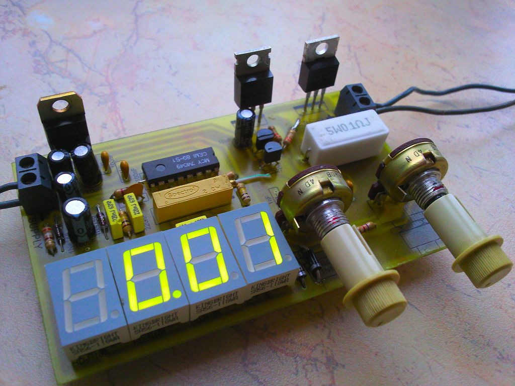
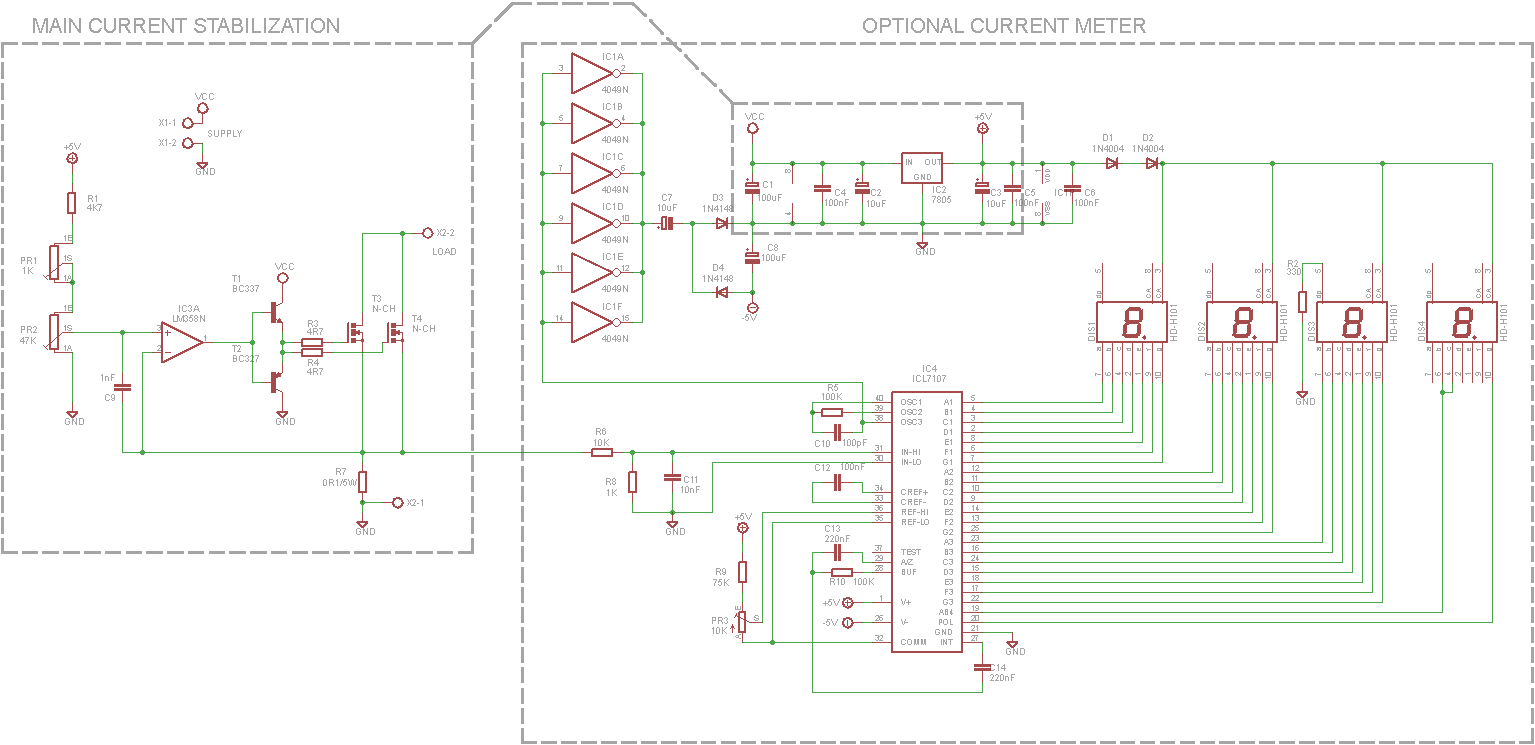
This simple system can be used to test the power supplies of various kind. The system behaves like a resistive load, expect that on the fly, using a potentiometer we can fix any load from 10mA to 20A and this value will be maintained regardless of the voltage drops. A value of current flowing is continuously displayed on the built-in ammeter. The system is very useful – it can be applied in each workshop. LM358 operational amplifier aims to the put voltage on the R7 was equal to the voltage set using PR1 and PR2 potentiometers. Potentiometer PR2 should be focused roughly, and PR1 accurately. Resistor R7 and transistor T3 (+ T4) should be chosen adequately to the maximum power we want to destroy on our load.
Transistor
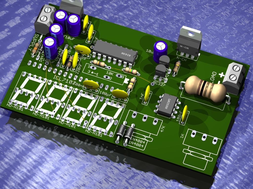
It can be any mosfet transistor with N channel. The operating voltages of the artificial load depends on its operating voltages. The parameters of our interest are: Id (drain current) and Pd (power dissipation). Id is the maximum current that can be let go by the connector, and Pd is the power of the losses which may be provided by the housing of the transistor. In this case, the transistor IRF3205 – theoretically – allows the load with current 110A, but its maximum power is dissipated to 200W and in almost ideal conditions (housing temperature Tc 25 degrees Celsius). The maximum current 20A can be fed at the operating voltage to 10V. To increase there parameters, two transistors connected in parallel were used, which allow dissipate up to 400W of power under ideal conditions 25 degrees Celsius. For this, a real powerful heat sink with forced cooling is needed. BC327 and BC337 are repeaters for mosfet transistors, they allow for quick reloading the capacity of gate. Capacitor C9 is a frequency compensation, it prevents the induction of the system. It was added “in reverse”, but as it turned out, in this case, the system does not induct. However, when testing pulse power supplies, it may be that the system inducts. In that case, you can solder C9 – stability speed will be lower then.
Resistor
When the load is 20A, the resistor should have a power of 40W and be well cooled. 20A * 0R1 = 2V. 2V * 20A = 40W. The best is a resistor with metal housing with the possibility of screwing the heat sink. You can also combine multiple resistors in order to obtain 0,1ohm of a suitable power.
The supply voltage is unregulated 15V, although it still depends on the Vgs parameter of the transistor, the gate voltage at which the transistor is fully open. Normally you do not need more than 10V. At a higher voltage, the stabilizer IC2 should be equipped with the heat sink. Also a transistor version of Logic Level (TTL voltages controlled) can be used. Then 7V power supply is fully sufficient.
Notes
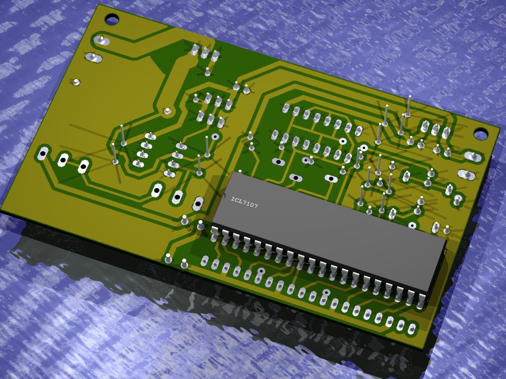
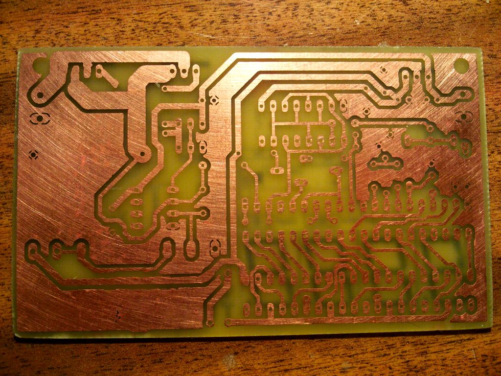
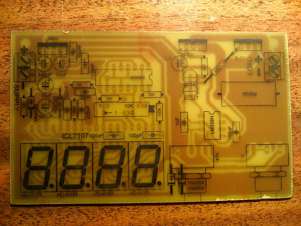
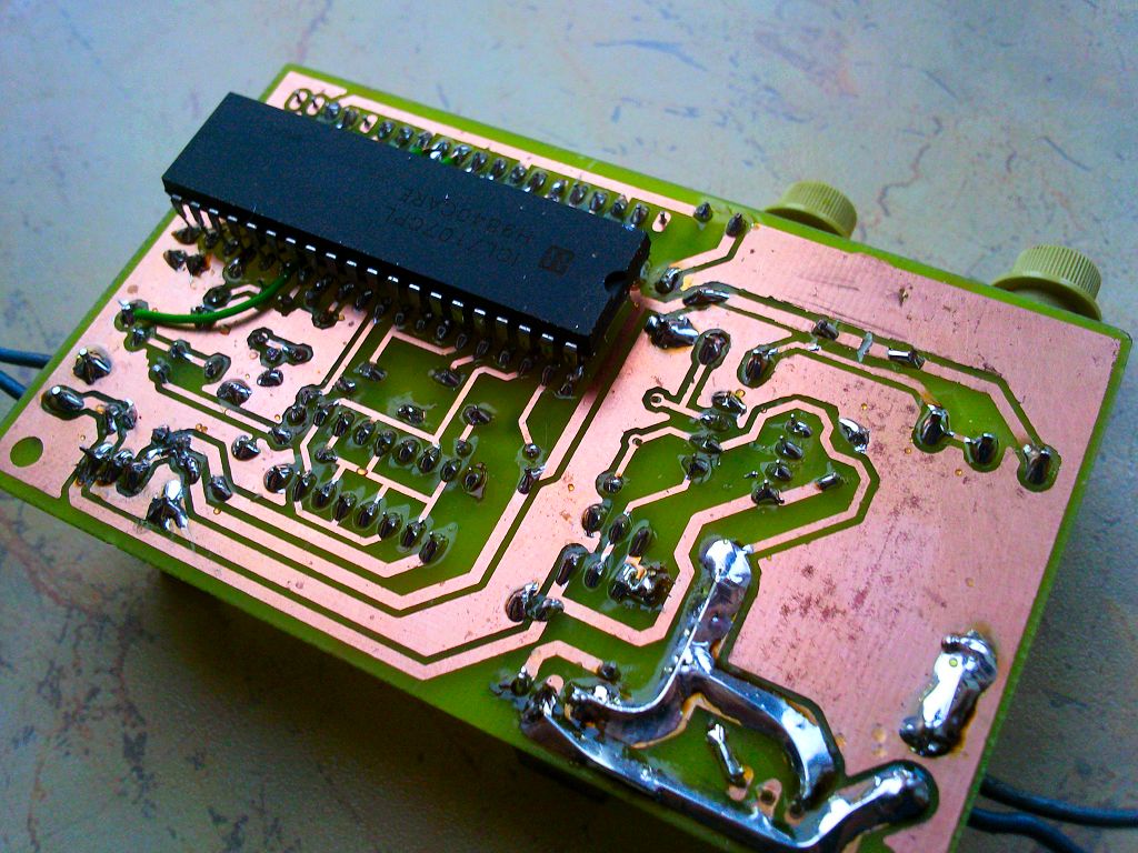
ICL7107 system should be soldered from the print side. It was designed in a way that requires it. LEDs are 14mm with a common anode. There should be three connections by insulated cables made on the PCB. The power of load may be increased by adding more mosfet transistors, but accordingly to rules of connecting such transistors. They do not require compensation resistors, because with increasing temperature, the resistance of RDSon connector increases and current distribution will be aligned. Each transistor must have a separate resistor on the gate. Current paths (marked by dashed line) should be bold.
Running
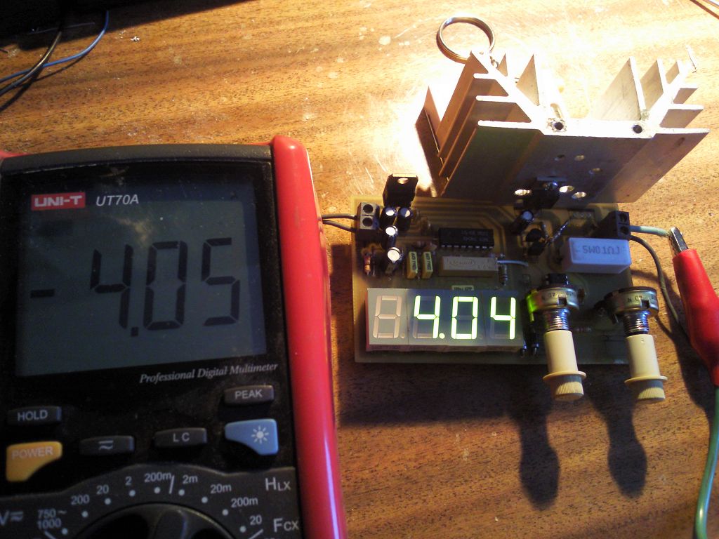
The meter indications should be calibrated. Run the system, add tested power supply to the LOAD terminals, and in series with it add a multimeter set to measure current (range 10A). Set the same indications as in the multimeter using PR3 potentiometer, except that such a calibration should be performed after warming up the system.
Other applications of the system
The system can also be used to test batteries, accumulators. Comfort measuring and counting their capacitance is easy because of the stabilization of power, which will always remain at a specified level. The system can also be used as an ordinary current meter or as the power supply current limiting – it can be connected in series with a receiver and both of these options would be available at once. To measure current, turn control knobs to the far right, so that the transistor was always open – then the voltage drop occurs only at the measuring resistor.
Note! - a bug in documentation – PR2 potentiometer should be 4,7K.
Link to original thread (attachment) – Sztuczne obciążenie o regulowanym prądzie