Continue to Site

Welcome to EDAboard.com

Welcome to our site! EDAboard.com is an international Electronics Discussion Forum focused on EDA software, circuits, schematics, books, theory, papers, asic, pld, 8051, DSP, Network, RF, Analog Design, PCB, Service Manuals... and a whole lot more! To participate you need to register. Registration is free. Click here to register now.

Bandpass filter design help needed

Status
Not open for further replies.

A3ynn

Newbie level 3
Joined
Oct 19, 2011
Messages
3
Helped
0
Reputation
0
Reaction score
0
Trophy points
1,281
Activity points
1,303
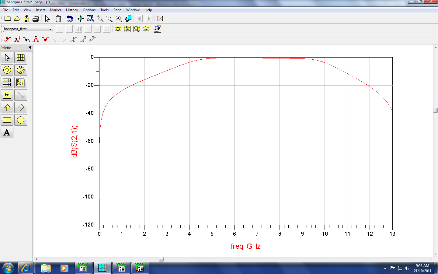
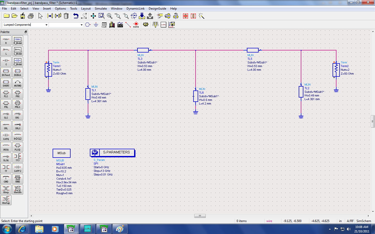
Hi. I need to design a bandpass filter of bandwidth 3.1GHz to 10.6GHz with centre frequency of 6.85GHz. But i didnt manage to get the passband (from 3.1GHz - 10.6GHz). I only had the waveform which i have attached it. Also my lecturer did say about using half-wavelength for TL3 and TL5, and quarter-wavelength for TL1,TL6,TL2 (Schematic attached). I had no idea how to change them to those assigned wavelengths. Is that the reason why i couldnt achieve the passband? Please help. I'm lost. Thanks.


1.

It looks like you have 5 inductors. Did you progress to this point step by step, while observing what the response graph looks like with 2 inductors, then 3, etc? (Or whatever series of steps leads up to what you have now.)

2.

Is this network an outgrowth of one with fewer components? Perhaps the values you'd use with a 3 inductor network would not necessarily work for a 5 inductor.

3.

The inductors influence each other. Hence changing one value alters the time constant seen by other components. Possibly requiring that you change their values as well?

4.

Did you set the inductor values according to a formula that is supposed to apply to all 5 in a network?
Or have you tailor-adjusted each value individually to meet a desired rolloff curve?

5.

Your specs give length and diameter. Is the simulator treating these all as single layer air core? Are these figures meant to yield a certain Q, or some other characteristic?

---------- Post added at 17:51 ---------- Previous post was at 16:45 ----------

After looking at your graph again I guess you mean that the curve should start dropping immediately to either side of 6.85 Ghz. A bell shape.

Your center frequency appears okay. However you have a plateau rather than a bell.

This means the part of your network that attenuates low frequencies has too high of an overall millihenry (or microhenry) value.

And the part of the network that attenuates highs has too low a value ... I think. If it were a speaker crossover then I'd say the tweeter was getting midrange emphasis which is a sign of too high uF capacitor inline. Since you're using inductors it gets me mixed up, so switch it around whatever way is correct.
 

Microstrip filter can't reach so wide bandwidth, you must use special microstrip structure to do it.
 

You should increase the number of sections that will cost you in-band ripple and attenuation.
 

what kind of software that u used?
 

Status
Not open for further replies.

Similar threads

Part and Inventory Search

Welcome to EDABoard.com

Sponsor

Back
Top