Continue to Site

Welcome to EDAboard.com

Welcome to our site! EDAboard.com is an international Electronics Discussion Forum focused on EDA software, circuits, schematics, books, theory, papers, asic, pld, 8051, DSP, Network, RF, Analog Design, PCB, Service Manuals... and a whole lot more! To participate you need to register. Registration is free. Click here to register now.

[SOLVED] PICKit 3 Demo Board - Program does not run!

Status
Not open for further replies.

zia.newversion

Member level 5
Joined
Mar 28, 2010
Messages
83
Helped
1
Reputation
2
Reaction score
1
Trophy points
1,288
Location
Pakistan
Activity points
2,188
The project file is attached.

I am trying to build and load this LED-ON program on my newly acquired PICKit 3 Demo Board (w/ PIC18F45K20). Everything is fine, the programmer is supposed to be powering the board, the voltage is set to 3.25V, there is no error in build, there is no error in programming/verifying. YET, the LED refuses to glow.

And in Debugger -> Settings -> Status (Tab) the PICKit3 VDD is 0.00V... I can't get it. The program was downloaded from Microchip websites and is supposed to be an introductory lesson for PICKit3 Debug Express...

If someone could kindly have a look at the code and explain what I am doing wrong, I shall be duly grateful.
 

Attachments

  • LED.rar
    14.7 KB · Views: 38

Everything is fine, the programmer is supposed to be powering the board, the voltage is set to 3.25V, there is no error in build, there is no error in programming/verifying. YET, the LED refuses to glow.

Are you running this in debugger or programmer mode? If debugger mode, once the PIC is programmed and verified, have you then issued the "RUN" command? If programmer mode, have you then issued a "Release from Reset ..." command.

And in Debugger -> Settings -> Status (Tab) the PICKit3 VDD is 0.00V... I can't get it. The program was downloaded from Microchip websites and is supposed to be an introductory lesson for PICKit3 Debug Express...

I do not have a PICkit 3, so I can not advise you effectively on its setup.

BigDog
 

Are you running this in debugger or programmer mode? If debugger mode, once the PIC is programmed and verified, have you then issued the "RUN" command? If programmer mode, have you then issued a "Release from Reset ..." command.

I have tried running in both modes with the same result. Also, in debugger mode, I tried issuing the Run command, the Animate command and Release from Reset comman, to no avail.
It's strange. I would have assumed that the board is faulty. However, that is out of the question since in that case, the board would not connect to PICKit 3 at all, not to mention return alright on Program and Verify commands!
 

I have quite a few Microchip development boards, in the order of about two dozen. And I have never received a bad board from Microchip, so they appear to do quite a good job as fair as quality control.

Therefore, I seriously doubt it is the board, besides there are only a few possible points of failure. I'm leaning towards a power supply issue. Perhaps the PICkit is not setup properly to provide the necessary power to the board. Let me see if I can track down the boards schematics.

BigDog

---------- Post added at 02:04 ---------- Previous post was at 01:38 ----------

Try this version of the code, using the same linker script, etc as outlined in the PICkit 3 Debug Express Lessons User's Guide:

Code:
/***********************************************************
	First PIC18 Program Ever!!!
***********************************************************/

#pragma config FOSC = INTIO67
#pragma config WDTEN = OFF, LVP = OFF

#include "p18f45k20.h"


void main (void)
{
	TRISD = 0b01111111;// PORTD bit 7 to output (0); bits 6:0 are inputs (1)
	LATDbits.LATD7 = 1;// Set LAT register bit 7 to turn on LED

	while (1);
}

The only major difference is the MCLR is not disable in this version, which I would think the PICkit 3 would need to Reset the board.

Also, have you tested the Vdd from the PICkit with a multimeter to see if indeed it is providing 3.25V?

BigDog
 
Last edited by a moderator:

@BigDog

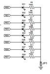
Thanks a lot. I just figured it out. There wasn't any problem with the code, programmer or the board per se. I just needed to short JP1, which bypasses the current limiting (that's what I think they are) resistors connected in series with all LEDs and it's all working now. The voltage drop across the LED was not enough. I figured out the problem when my hand accidentally touched the resistors and the LED started visibly glowing. When I removed the hand, it went back to as it was. So, I took a jumper and put it on JP1, and all of the lessons are working now.
 

I just needed to short JP1, which bypasses the current limiting (that's what I think they are) resistors connected in series with all LEDs and it's all working now.

Actually JP1 completes the circuit by tying the all the diodes to ground, the current limiting resistors are always necessary with components like LEDs.

PICkit3DevBoard.jpg

I'm glad you managed to get it working.

BigDog
 

Oh... I should probably study the schematic before getting to any further experimentation. :p

Thanks a lot BigDog
 

Status
Not open for further replies.

Similar threads

Part and Inventory Search

Welcome to EDABoard.com

Sponsor

Back
Top