Continue to Site

Welcome to EDAboard.com

Welcome to our site! EDAboard.com is an international Electronics Discussion Forum focused on EDA software, circuits, schematics, books, theory, papers, asic, pld, 8051, DSP, Network, RF, Analog Design, PCB, Service Manuals... and a whole lot more! To participate you need to register. Registration is free. Click here to register now.

ribbon cable on pcb design

Status
Not open for further replies.

yougarage

Member level 1
Joined
Apr 13, 2011
Messages
38
Helped
0
Reputation
0
Reaction score
0
Trophy points
1,286
Activity points
1,599
Hi all!
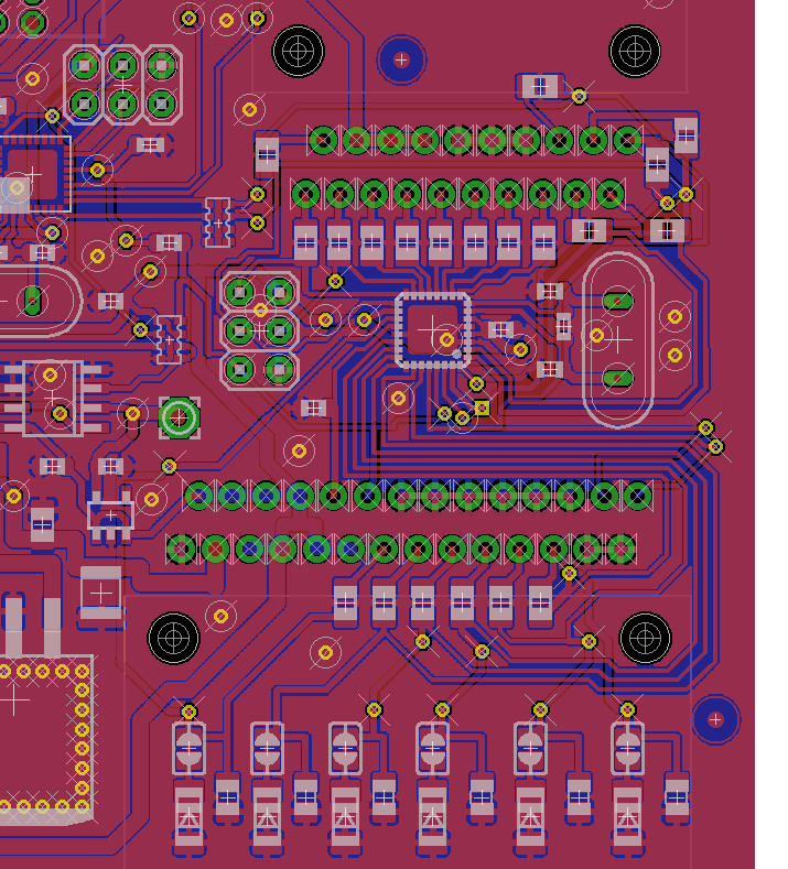
I'm designing a pcb, but in a section of this, the traces are very convoluted, because they have to "turn around" a big trough hole component.
I was wondering if it's a good practice to "jump" the trough hole component using a ribbon cable instead of keeping long and convoluted traces
and if you can suggest me any brand or series to use
It would be a very short lenght, about 20 millimeters and the signals on it are very low current
 

The whole point of a PCB is it is a cheap, mass produced, automated part. To add a ribbon cable to jump over a part seems crazy except in exceptional circumstances. Maybe you could show what the problem is.

Keith
 

sure here it is.
You are right, I'm a novice in pcb design, any advice is greatly welcome.
You can clearly see in the pic where is the messy zone I'm talking about...
the trough hole component is a connector,

---------- Post added at 09:34 ---------- Previous post was at 09:32 ----------

sure here it is.
You are right, I'm a novice in pcb design, any advice is greatly welcome.
You can clearly see in the pic where is the messy zone I'm talking about...
the trough hole component is a connector


Can the connector be rotated 180 degrees? Are the pin definitions pre-defined? Also, you could go between the pins rather than round. If the pads are too large you could reduce them - you don't have to stick to the library sizes.

However, it doesn't matter unless you feel the long route will affect functionality.

Keith
 

The connector can't be rotated, but the pins are not assigned.
I thought I could pass between the pads but I was not sure about it. The pins pitch of the connector is 2.2 mm
Do you think it could be safe to go between them with a 10 mils track?
If I reduce the pads size, could it affect the mechanical resistance to vibrations?
The circuit works this way, analog signals arrive to the connector, then pass trough the resistor, and go to the capacitor, to form a lowpass filter.
additionally there is a zener for each signal to protect from overvoltages, that I can exclude cutting the solder jumper.
maybe I just should shorten the track between the resistor and the capacitor to keep the lowpass filter effective.
Thanks for your help!
 

I would probably edit the connector and go between the pins. If you are concerned about the integrity of the connection you could use the oval pads instead of round - that would give a decent pad with a wider gap. 10 thou is fine - most places can make 6 thou with no problem although I like to use the largest possible design rules.

Keith
 

thanks!oval pads seems the best solution!
 

Status
Not open for further replies.

Similar threads

Part and Inventory Search

Welcome to EDABoard.com

Sponsor

Back
Top