lloydi12345
Member level 4
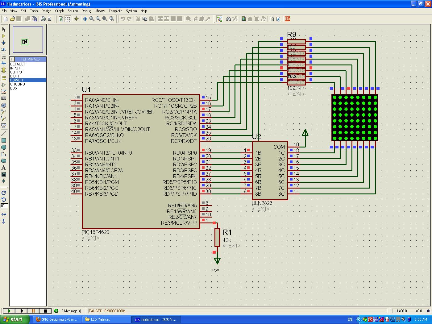
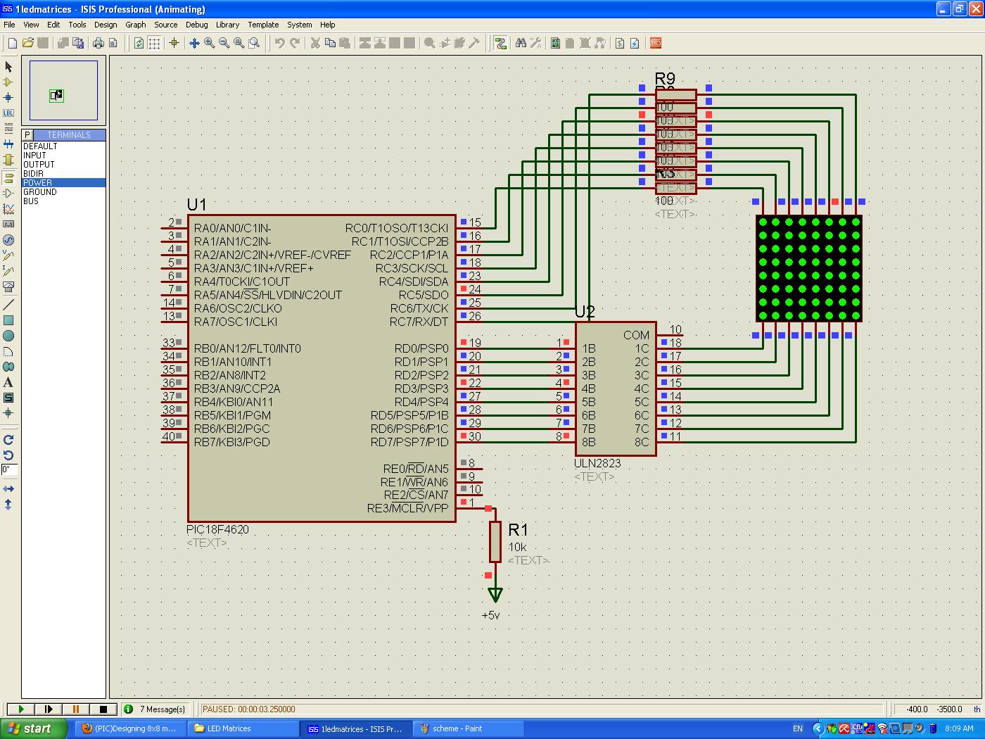
I'm interfacing an 8x8 LED Matrix Dot Display for showing characters and made them successfully however I would like to redesign my schematic since it's involved with more components. I believe the simpler is the better. Here's my schematic:
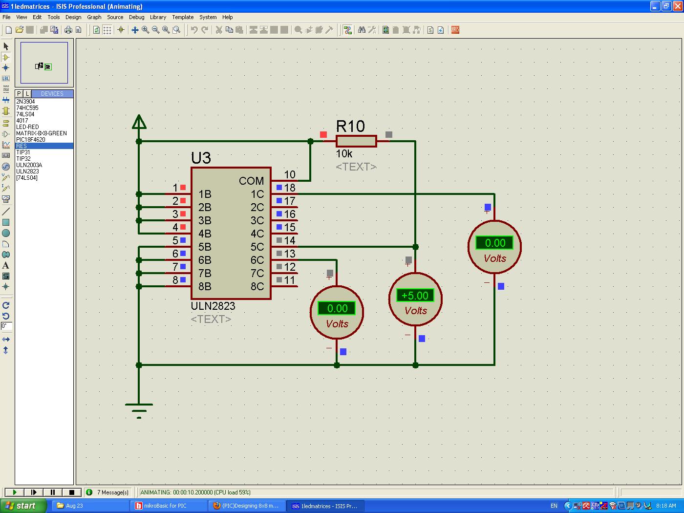
I've seen design that connects their COM pin to Ground and the rows are directly connected to the darlington arrays with no resistors. How can I do this? I tried grounding my uln2323's COM pin but when I produce any logic values the output of ULN2323 still stays ground. Here's what's happening:
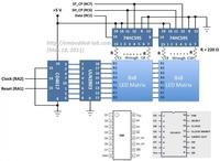
I would like to base my design to this design.
Thanks and regards :razz:,
lloyd
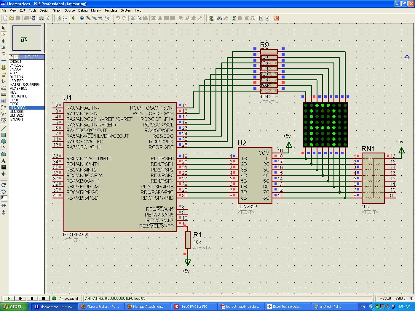
I've seen design that connects their COM pin to Ground and the rows are directly connected to the darlington arrays with no resistors. How can I do this? I tried grounding my uln2323's COM pin but when I produce any logic values the output of ULN2323 still stays ground. Here's what's happening:

I would like to base my design to this design.

Thanks and regards :razz:,
lloyd
") ). If the PIC outputs are driving the 8 rows (which are the ANODES of the LEDs), and the ULN2823 is connected to the cathodes of each column, then, yes, you don't need the pullups.
). If the PIC outputs are driving the 8 rows (which are the ANODES of the LEDs), and the ULN2823 is connected to the cathodes of each column, then, yes, you don't need the pullups.