Continue to Site

Welcome to EDAboard.com

Welcome to our site! EDAboard.com is an international Electronics Discussion Forum focused on EDA software, circuits, schematics, books, theory, papers, asic, pld, 8051, DSP, Network, RF, Analog Design, PCB, Service Manuals... and a whole lot more! To participate you need to register. Registration is free. Click here to register now.

AD7621, DNL & INL parameters

Status
Not open for further replies.

Fisquietto

Newbie level 4
Joined
Aug 30, 2011
Messages
6
Helped
1
Reputation
2
Reaction score
1
Trophy points
1,283
Activity points
1,321
Hello,

We want to evaluate the performance of the CAN 16 bits AD7621. First of all, we want to extract the Differential non linearity and the integral non-linearity.

For that, the CAN is soldered on PCB board ( based on the evaluation board). We use a ultra low distortion function generator to drive the input of the device through 2 AD8021. The frequency is roughly 240 Hz

The sample clock is provided by a basic function generator.The frequency is 3MSPS

To extract the DNL and INL, we catch a lot of digitized data. we strobe the Busy output to be sure of data

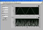
When we compute the histogram, a lot of code are missing. At every run, the same codes are missing. Strange !!

a screenshot of the histogram is attached.

If you have an idea, Thank for your help.
 

Attachments

  • histo.JPG
    histo.JPG
    119.7 KB · Views: 71

May be your clock frequency is an integer multiple of the sample frequency?
Try to make it at least an odd or prime -- or even better -- a non-integer multiple!
 

I already change the frequency of the input signal and I have the same result. The snapshot is for a frequency of 91.645 Hz.
 

The problem may be caused by digital (ADC data interface) to analog crosstalk.
 
How can I confirm or verified that there is disturbance between analog and digital signal?
 

I would check with different timing of the interface signals. Another explanation for linearity errors can be insufficient power supply bypassing or bad ground net layout.
 
Your missing codes seem to be equidistant with a period of 32 . Don't know if this can help.
 

Yes, and I don't known why. I change the frequency of the input signal, the sample frequency. The same codes are missing
 

2^16 - 1 is a rather low sample number for histogram testing of a 16bit converter. Did you already try to sample more than 2 periods of your input sine wave? And you should try and align the full sample time exactly to the total time of full sine wave periods. E.g. 327350 samples of 3MSPS for 10 periods of the 91.645 Hz sine wave. See pp. 22 ff. of the following presentation: View attachment Design_and_Test_Challenges_of_High_Performance_Data_Converters.pdf
 

The input sine waves and the samples clock are not synchronized. that's means that every codes should appear after a lot of acquisitions.

In the screenshot, the number of acquisition is more than 65535. For exemple, code 51680 occurs 40000 times while codes before never occurs
 

In the screenshot, the number of acquisition is more than 65535. For exemple, code 51680 occurs 40000 times while codes before never occurs

Right, I had been vexed by the given number of samples in your screenshot and didn't notice the occurrences denomination at the y-axis, sorry!
Did you ever try a second chip? Pls. tell us if you find out the reason for these equidistant missing codes!
 

I tried number of components, I called Analog devices. For them, there is no user return for this converter. I used another test bench, same behavior
 
  • Like
Reactions: erikl

    erikl

    Points: 2
    Helpful Answer Positive Rating
Status
Not open for further replies.

Part and Inventory Search

Welcome to EDABoard.com

Sponsor

Back
Top