31023102
Newbie level 2
Hi, i am doing the school project of ECG design now.
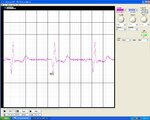
and the signal i obtained from scope is shown below

it seems that the output signal shows P Q R S and T wave; however, there is something wrong about Q wave. related material says that a health man should have a S wave deeper than Q wave( i m in good condition now~~)
Can someone tell me what's wrong inside my schematic? how to improve that?
Here is the schematic:

the bode plot simulated by cadence is shown below (green)

Thank you^_^
and the signal i obtained from scope is shown below

it seems that the output signal shows P Q R S and T wave; however, there is something wrong about Q wave. related material says that a health man should have a S wave deeper than Q wave( i m in good condition now~~)
Can someone tell me what's wrong inside my schematic? how to improve that?
Here is the schematic:

the bode plot simulated by cadence is shown below (green)

Thank you^_^