Continue to Site

Welcome to EDAboard.com

Welcome to our site! EDAboard.com is an international Electronics Discussion Forum focused on EDA software, circuits, schematics, books, theory, papers, asic, pld, 8051, DSP, Network, RF, Analog Design, PCB, Service Manuals... and a whole lot more! To participate you need to register. Registration is free. Click here to register now.

MOSFET Burning Out need help

Status
Not open for further replies.

Chullaa

Advanced Member level 4
Joined
Aug 27, 2010
Messages
113
Helped
17
Reputation
34
Reaction score
17
Trophy points
1,298
Activity points
2,019
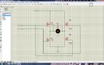
I am using IRF540 for my H-bridge circuit and using Power Window motor of automobile, my motor take 1.7 A at free run. According to data Sheet IRF540 should handle 22A easily but my transistor are burning out... i am afraid this is due to starting current of of motor which i dont know how much is.

Any one could help me plz about this. and one more thing what is stall current.
Regards

IRF540
http://www.datasheetcatalog.org/datasheet/stmicroelectronics/9387.pdf
 

Please post your circuit.

Chullaa said:
my motor take 1.7 A at free run

You mean with no load?
 

Post your circuit diagram..

How do you drive the High side mosfets?
You may need a high side driver
 

Voltage? Mosfet Driver? You can measure the current easily using a shunt power resistor with the motor.
 
This is schematic diagram i am using. 12 VDC Power Supply(5A X 12V).

Inputs are being controlled by 5 volt dc separately.
 

Attachments

  • HB.jpg
    HB.jpg
    366 KB · Views: 190

prot.jpg

Hi i am using this simple circuit to switch the MOSFET (IRF540) turned ON and OFF. I applied 12V at drain and 5 volt at gate. and getting 1.9V approx. at source which at not enough to drive LED at its full brightness. If i use 12V at gate i almost provide 9.8V. is there anyway that i could get 12V (ideal) at source by applying 5V at gate. <Gate is supposed to be driven by microcontroller later on.>
Thanks
 

You can't do what you want with a high side N mosfet.
You either have to connect it as a low side switch or provide a gate voltage higher than the drain voltage.
Another alternative is to use a P mosfet (high side), in that case a simple NPN transistor would be able to drive the gate correctly so that the 0-5v mcu voltage is translated to 0-12v for the mosfet gate

Alex
 

**broken link removed**

is this the circuit i can use?
 

You don't need a complicated circuit, something as simple as that will work fine

Nmosfet_drive.gif

You can use a higher value resistor in the collector if you want, depends on the sped you want.
The power supply can be 12v without problem, and you can also remove the 10 ohm resistor.

Alex

P.S. I was referring to the circuit of post #7, if you were asking for a complete H bridge your link seems fine
 
thanks! i got the point. I have looked for some H bridge tutorials which explains its theory e.g. using catch diodes and advantages of using P-channel at High side so on. one more thing i want to know is how can we use effective breaking system (other than mechanical breaks). for my robot weighing about 14 Kg and i am using Window motor which takes continuous current of 1.7 A (I observed 23A stall current as well).

CHulla


how can we use effective breaking system (other than mechanical breaks)


When motor speens and suddenly you leave its edges floating, you have a spinning conductor inside a magnetic field and so a generator. If then you short the edges, then you would short the generators edges, so its voltage tends to go to zero. Generator voltage to zero (and since the magnetic field is still there) means no spinning so this is how you break the motor, by shorting its edges.
 

hmm thanks alexan and alexxx!
Today i used H bridge (all 4 N channel). I operated 3 DC Motors (15mAmp, 160 mAmp and 2.5Amp ). The two small motors worked fine. but when i tried to run 2.5Amp motor which is (geared) power window motor it ran very slowly with 1Amp. (with direct supply it takes 2.5Amp) and my left side (upper and lower left) IRF540 MOSFET got really HOT. I had to turn off the supply.
Now i wonder why is it so... Motor winding has resistance of 6 Ohms which may cause current to flow through MOSFETS rather than motor.
please need help about this.
 

Chullaa said:
Today i used H bridge (all 4 N channel)

How did you create the Vgs to make the upper FETs to conduct? Please post your circuit, maybe the overheating problem will become clear.

EDIT:
Sorry Alex, we were typing at the same time. :smile:
 

oh sorry about not mentioning the circuit...:roll:

I am using circuit at post #5. Supply voltage are 12 volt and gate voltage are 15V. using IRF540 so hopefully don't need to install Schottky's because they are internally installed in IRF540.
Today i consulted one of my teacher. he said me that MOSTFETs are being heating because i am not using gate resistor. Do We install Drain resistor as well? and for what reason.
i will implement the gate resistor today and will wait for your response.

CHulla :)
 

The circuit is not correct. High side mosfet are not correctly driven. You need an external driver or a p mosfet.
 

oh sorry about not mentioning the circuit...:roll:
I am using circuit at post #5. Supply voltage are 12 volt and gate voltage are 15V.

Unfortunately this is not enough, the gate threshold voltage of your mosfet is 2v-4v according to the datasheet and at that voltage the mosfet is just turning on , you need a Vgs higher than 4v , ideally you want about 10-12v to have the lowest possible Rds-on but even 5v (which means 12+5=17v) should do the job.
At your current gate voltage the Vgs of the high side (15v-12v=3v) leaves the mosfet in a half open state and it gets hot, the lower side mosfets are driven fine.

Today i consulted one of my teacher. he said me that MOSTFETs are being heating because i am not using gate resistor. Do We install Drain resistor as well? and for what reason.

he said what...8-O
The gate resistor is irrelevant to your problem, it in normally used to control/limit the gate current (which control the switch-on and off times) and help prevent parasitic oscillations.
A drain resistor is not needed, it will only limit the output current and I don't see a reason for that.

Alex
 
thank you!
i understand it now. I am using a 5A supply which is providing about 12V. I am going to buy new dry batteries tomorrow and buy some BJT transistors to drive MOSFETs. To provide better threshold voltage. I will let you know when i done it :grin:
 

Status
Not open for further replies.

Part and Inventory Search

Welcome to EDABoard.com

Sponsor

Back
Top