Continue to Site

Welcome to EDAboard.com

Welcome to our site! EDAboard.com is an international Electronics Discussion Forum focused on EDA software, circuits, schematics, books, theory, papers, asic, pld, 8051, DSP, Network, RF, Analog Design, PCB, Service Manuals... and a whole lot more! To participate you need to register. Registration is free. Click here to register now.

Lame question-simulating simplest AC/DC+buck converter in PSPICE

Status
Not open for further replies.

gazownik

Newbie level 4
Joined
Jun 19, 2011
Messages
6
Helped
0
Reputation
0
Reaction score
0
Trophy points
1,281
Activity points
1,355
Hello everyone, I'm totally new here, so I'll just start from the beginning:

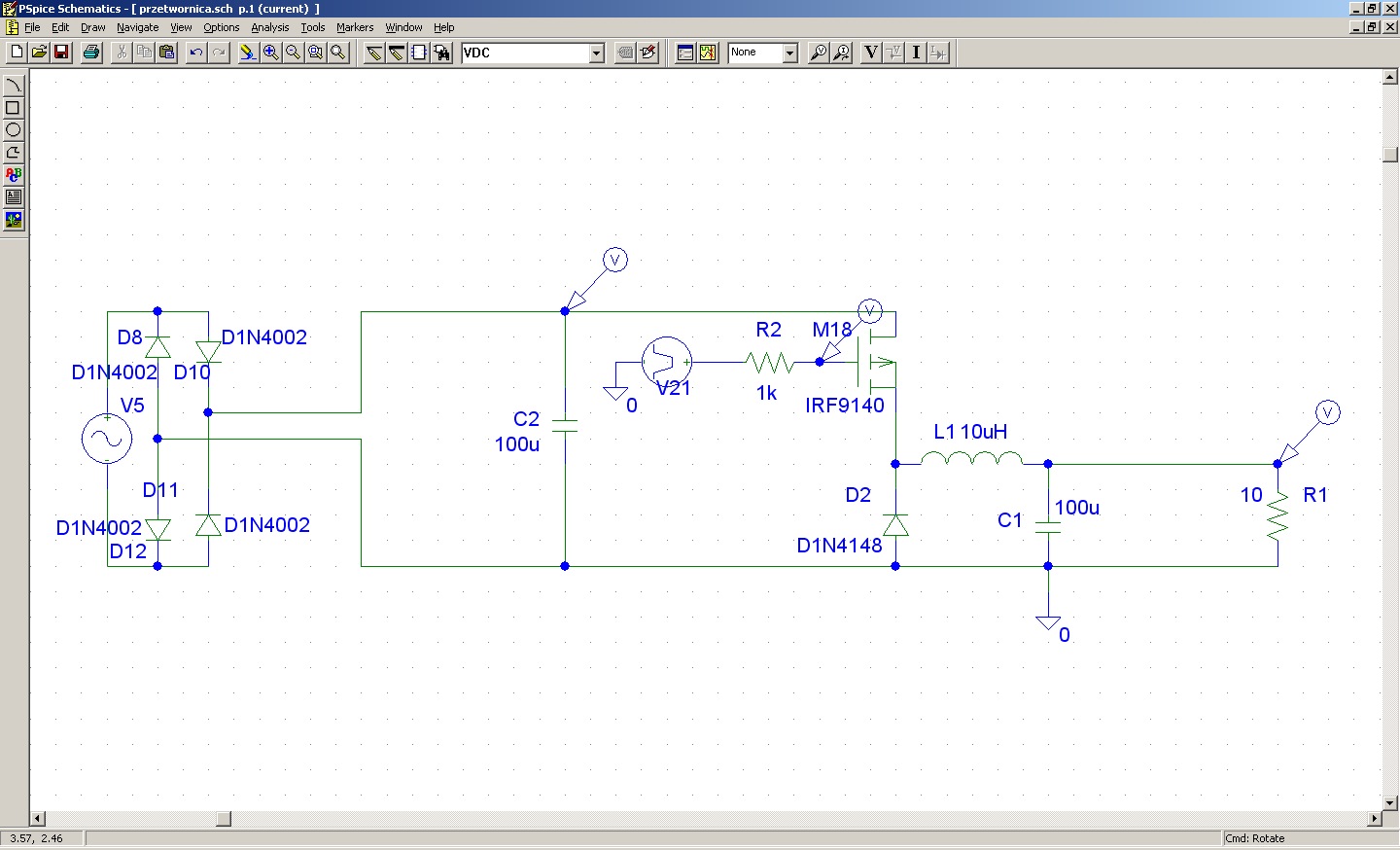
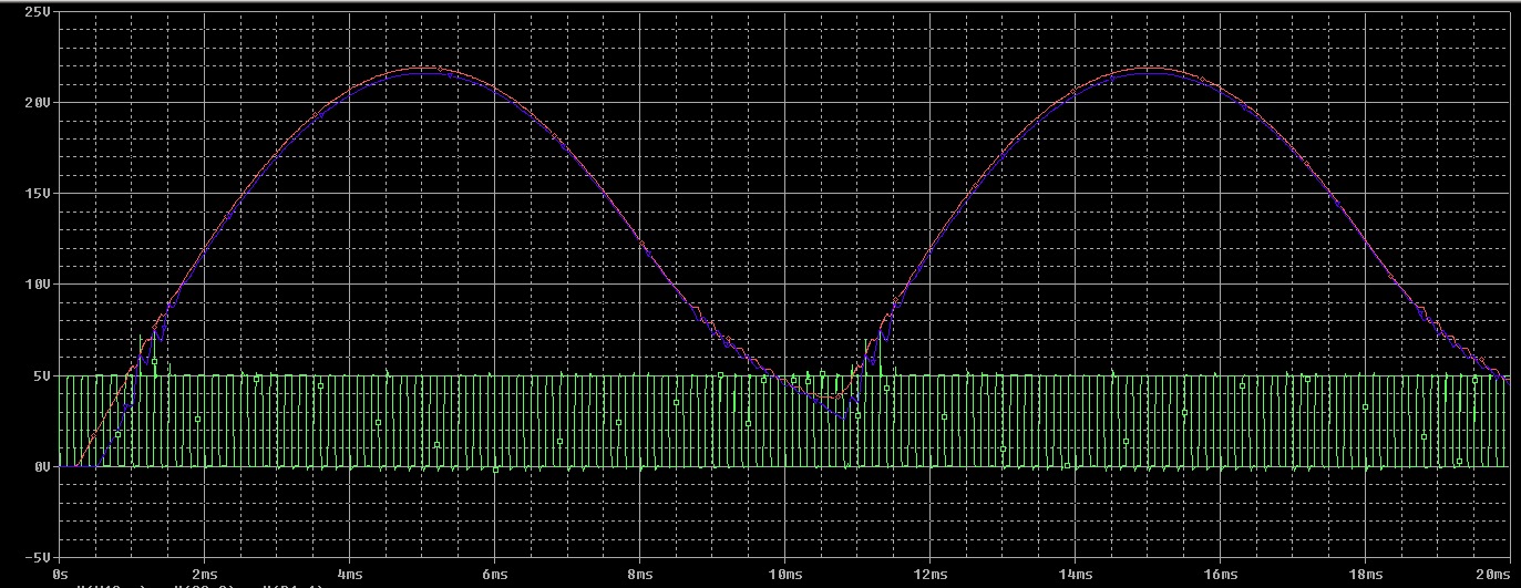
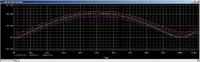
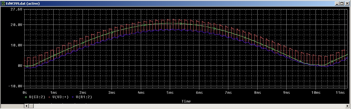
For the past few weeks I've been trying to properly simulate the behaviour of a simplest AC/DC circuit (i.e. Vsin simulating the stepped-down voltage from the transformer output + full wave rectifier + capacitor for filtering) and a buck converter. The point is, I'm almost sure i'm not getting something right, as the simulation brings up results not exactly up to my expectations. Please, have a look:


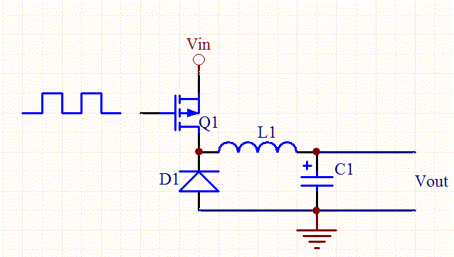
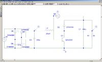
And this is the mentioned circuit:


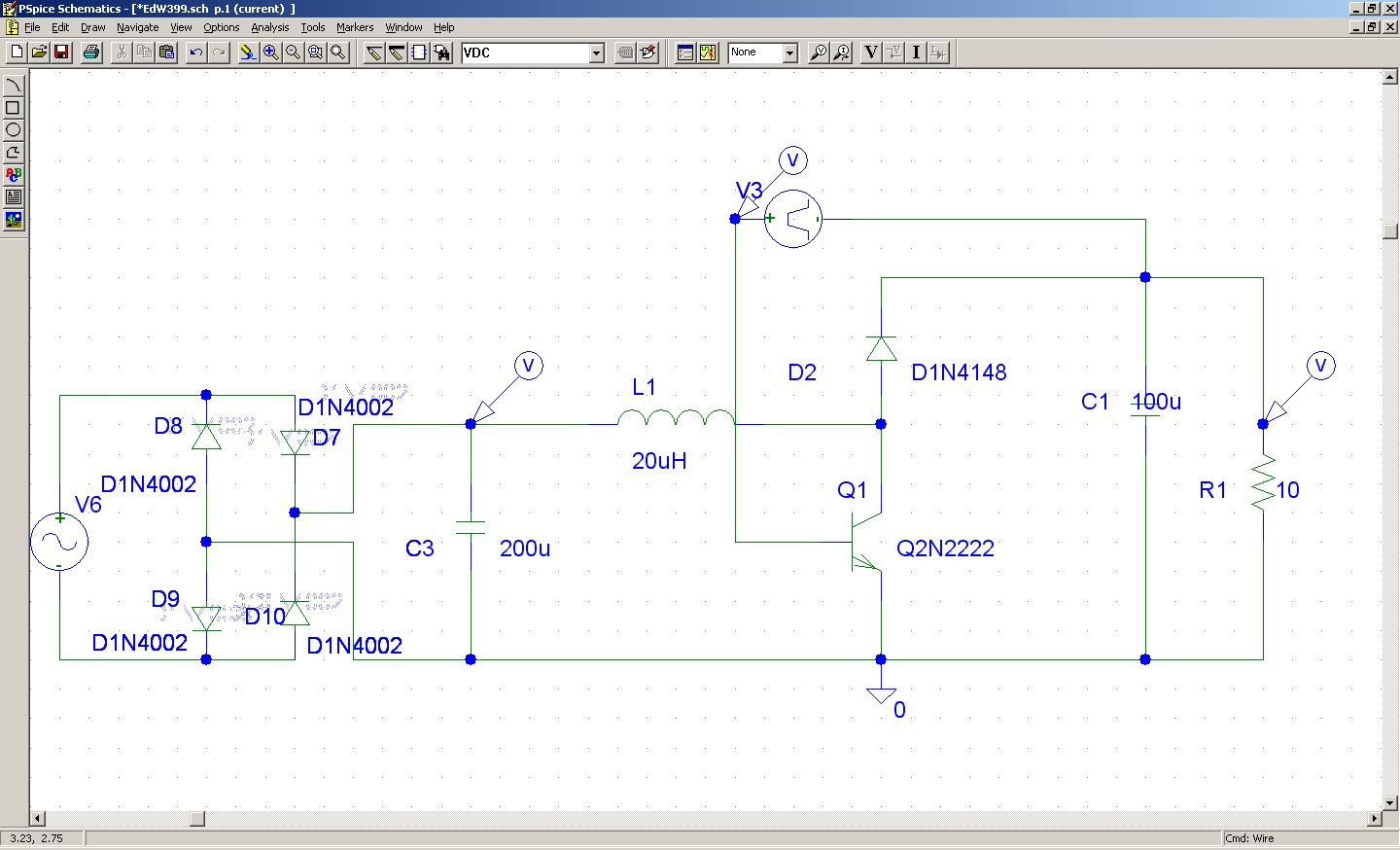
Vpulse parameters are TD/TR=1u PW=100u, PER=200u, V1=5 V2=0


Does the circuit need some galvanic separation behind the filtering capacitor? What am I doing wrong? Please help, thanks in advance.


I'm also attaching a .zip contatining complete PSPICE schematics.

Best regards.
 

Attachments

  • PSpice.zip
    2.4 MB · Views: 72

That's a boost converter not a buck. Also, you need a sensible base drive circuit for the transistor (e.g. A base resistor) and drive it with a voltage with respect to ground, not the output voltage. Maybe you are hoping that will provide feedback but it will just short out the output with the transistor as the output voltage rises.
You could do with using a power Schottky diode and a MOSFET would be more suitable than a 2N2222, I would have thought.

Keith
 

Thanks Keith,

As I said-this is something totally new to me, so I guess I'm going to do a lot of mistakes while learning.

The circuit I posted above is the newer one, while the first one I tried to simulate was as follows:


This one had its Vpulse in referrence to the ground, the 1k base resistor is added according to your suggestion. The 1n4148 is sufficiently fast I suppose?

Its output is (almost) identical with the input, i.e.:


I realize that a MOSFET is better for that kind of a device. I just became frustrated at some point and tried a different approach, so that's why the bipolar is present there. The point is I just want to simulate the principle of operation properly, refining the circuit coming later.

I know I'm missing some basics here, I just can't figure out where. Thanks in advance for any suggestions.
 

Its output is (almost) identical with the input
Yes looks like something is significantly wrong!
- you put in a PMOS instead of a NMOS FET. It' simply acting as a short between input and output
- the circuit won't work with a NMOS FET either, because the gate driver voltage needs to be connected between source and gate (bootstrap or floating driver)
- finally you would want to use a diode with sufficient current rating

My general suggestion is to start with a buck converter circuit from a text book or tutorial.

It's also O.K. to assemble components arbitrarily and observe, what happens in the circuit. But you have to look sharp to identify the circuit faults on your own.
 

Many thanks for all your remarks, they are indeed helpful.

The biggest problem for me lies in determining how the particular transistors should be connected depending on their type, i.e. which and when.

Diagrams available on the net also confuse me a bit:


While I found this one in an article concerning the converter topic:


As you can easily see, the topic of "driver" on the pictures above is very vague for a newbie, with no clue about proper way of connecting the driver to the transistor-without clue how to connect that abstract "Vpulse" and forcing to guess between "GND-resistor-base" or "Vgs pulse feed". Therefore all my attempts aimed at simulating even simplest converter failed. I guess that this, together with the transistor issue described above is the source of my constant confusion.

What about the diode? Is the D1N4148 somehow lacking for conducting proper simulation?
 
Last edited:

The 1N4148 may be fast enough but will not handle the currents involved. Look for a decent Schottky diode in the simulator library. As you are using LTspice, try analysing the waveforms and components of one of their example circuits - there are loads of them included in the installation. Ignore the feedback mechanism, just look at the voltages and currents in the main devices to help understand it.

Keith
 

4148 is good for signal application and not for power usages. Schottky is best bet or you can use MUR470(since I do not know exact specification, just suggesting a part) or other device from MUR series. These are also very good for hard switching application upto 200KHz.
 

Status
Not open for further replies.

Similar threads

Part and Inventory Search

Welcome to EDABoard.com

Sponsor

Back
Top