Continue to Site

Welcome to EDAboard.com

Welcome to our site! EDAboard.com is an international Electronics Discussion Forum focused on EDA software, circuits, schematics, books, theory, papers, asic, pld, 8051, DSP, Network, RF, Analog Design, PCB, Service Manuals... and a whole lot more! To participate you need to register. Registration is free. Click here to register now.

TTL headaches: driving a BC bc557b

Status
Not open for further replies.

csdave

Member level 5
Joined
Feb 11, 2011
Messages
87
Helped
2
Reputation
4
Reaction score
2
Trophy points
1,288
Activity points
2,122
hi all again.
I am still playing with the logics of my pet fountain circuit before on the breadboard before I turn it into something real.

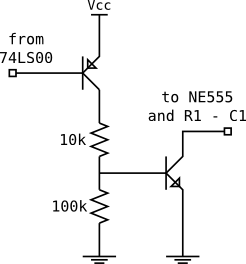
Without explaining long details I am using a 555 in monostable mode with a retriggering circuit using a bc557. Basically, the transistor (a PNP) is connected with collector into GND, and emitter at the + of the monostable capacitor (pins 6,7 on the 555) which is in turn, pulled up to Vcc by a charging resistor. Cap is 100uF and restistor O(1Mohm) to yield order of 100sec.

Things worked fine when I was driving the base of the bc557 from another 555 or from a 74HCT74. Tonight, however, I tried adding a different feature and since I had nothing else to use I stuck in a 74LS00 and tried driving the bc557 from it.

The transistor correctly discharges the capacitor when the output of the 74LS00 is low. However, when the output of the gate and the base of the transistor are high (4.3V approx) the capacitor does not charge above 2.5v. The base-emitter junction should be inversely polarized and the transistor should be off... but still it looks like it's stealing current from the capacitor!

What is the problem?

Thanks

Davide
 

give the circuit which give you problem(aka headache) and tell your requirement.
 

here is the incriminated portion of the circuit

**broken link removed**

and the whole circuit

**broken link removed**


I made some progress since saturday. I first tried with a different battery ( I was using NiMh 6 AA batteries all of which were almost fully charged and switched to an alkaline 9v battery, in both cases I had a 7805 providing power) and the circuit worked.
Then I replaced the 74LS00 with its HCT counterpart and got it to work on the AA batteries too, even though only for a few cycles.

So drawn current is the issue here. I checked with an ammeter and the the whole circuit with the omron G8P relay attached to it (in parallel with the flyback diode on the right) eats approximately 250mA when the relay is on. I thought this was low enough for those batteries, or are transient currents causing the problem?
I should mention that this was mounted on a breadboard (I am going to get a perfboard prototype done soon) so could that be the problem?

Finally, I have another question.
Do I need heatsinks for the two transistors?

the 2N2222 is either off or saturated, so no heatsink should be required right?

the BC557B however is not saturated (it can't be in that configuration). It is rated 200mA, but what is the current through it at the beginning of the discharge when there are around 3V on the capacitor?

thanks ;)

Davide
 

for the discharging bc557 problem:

connect a diode from bc557 base to output of the gate 74ls00.

anode of diode to base of bc557 and cathode to 74ls00 output.
any idode (1n4148 or if you dont have it connect 1n400x )

test and post the result.
 

Don't use old TTL ICs in the circuit because their minimum output high voltage is only +2.7V when the supply is +5V. A high speed Cmos 74HCxxx IC goes to the positive supply voltage if it is not heavily loaded.
 

Did the test.. for some reason tonight it worked seamlessly with and without diode as long as the relay wasn't connected. I am afraid I might have had some issues in the wiring earlier.

With the relay in the battery is simply not enough I am afraid... Although this puzzles me.

for the discharging bc557 problem:

connect a diode from bc557 base to output of the gate 74ls00.

anode of diode to base of bc557 and cathode to 74ls00 output.
any idode (1n4148 or if you dont have it connect 1n400x )

test and post the result.


---------- Post added at 00:37 ---------- Previous post was at 00:37 ----------

Don't use old TTL ICs in the circuit because their minimum output high voltage is only +2.7V when the supply is +5V. A high speed Cmos 74HCxxx IC goes to the positive supply voltage if it is not heavily loaded.

74HCTxxx are fine, aren't they?

---------- Post added at 00:38 ---------- Previous post was at 00:37 ----------

also, can anyone tell me what will be the current through the BC557 and whether I should add a heatsink anywhere?
 

Your problem is that the BC557 is in common-collector / emitter-follower configuration and will precisely follow the voltage on it's base - that's bad if you're using an LS part to drive it. If srizbf's **** (a level shifter by Vf?) doesn't help, you may want to redesign that section entirely for real switching. That would mean: put in a rail-referenced transistor (common emitter) for the switching job and an inverter for the right polarity.
Edit: the resistor values are uh, illustrative, randomly picked without thinking, duh. Hope you'll get it working either way ;-)
18_1301352676.png


Edit2: Quite a hot topic - missed the two preceding posts before sending, so sorry if this post looks somewhat unrelated to the last things said.
The transient current of BC557 will mainly depend on parasitic resistance of the C1. Look up series resistances of elyt. capacitors and see if you can work with that.
 
Last edited:

Why does your relay coil draw such a high current? It is killing your battery.
If the supply is +5V then the output high of the 555 is +3.65 then the base of the 2N2222 that drives the relay coil has a base current through the 400 ohm base resistor of only 7.4mA. If the relay coil needs nearly 250mA then the base current must be 25mA for the 2N2222 to saturate properly.
 

Your problem is that the BC557 is in common-collector / emitter-follower configuration and will precisely follow the voltage on it's base - that's bad if you're using an LS part to drive it. If srizbf's **** (a level shifter by Vf?) doesn't help, you may want to redesign that section entirely for real switching. That would mean: put in a rail-referenced transistor (common emitter) for the switching job and an inverter for the right polarity.
Edit: the resistor values are uh, illustrative, randomly picked without thinking, duh. Hope you'll get it working either way ;-)
18_1301352676.png

Circuit works fine with HCT and also with LS if the power supply is strong enough. Do you still suggest I redesign the PNP reset?

---------- Post added at 13:29 ---------- Previous post was at 12:37 ----------

mm I am not sure I am grasping everything yet. I am going to run a few more tests as soon as I have time ;)
 

Circuit works fine with HCT and also with LS if the power supply is strong enough. Do you still suggest I redesign the PNP reset?
No need. If it works, why complicate it? Just be wary about the LS part if you intend to use it there - it won't give true rail/rail hi/low levels.
 

Why does your relay coil draw such a high current? It is killing your battery.
If the supply is +5V then the output high of the 555 is +3.65 then the base of the 2N2222 that drives the relay coil has a base current through the 400 ohm base resistor of only 7.4mA. If the relay coil needs nearly 250mA then the base current must be 25mA for the 2N2222 to saturate properly.

how did you get the 25mA?
Relay actually requires 185mA. I realized that my original calculations were wrong, I had used 75 (but minimum is 35) and (shame) 5V on Vb as a first approximation and had forgotten to change it later ;). Thanks for pointing it out.

Now with 185mA I need
185/35 = 5mA and if I use the rule of thumb of 5 times Ibmin then I need Ib to be 25mA, yielding a resistor of (3.65-0.6) / 0.025 ~= 120ohm

with 250m the requirement should be higher shouldn't it?
250/35 = 7
7* 5 = 35 yielding 85 ohm.

Am I missing something?

---------- Post added at 18:54 ---------- Previous post was at 18:51 ----------

No need. If it works, why complicate it? Just be wary about the LS part if you intend to use it there - it won't give true rail/rail hi/low levels.

what I am unsure of is the fact that the PNP transistor is in the active (non saturated) region. And I wonder whether I need a heat sink for it. It doesn't seem to have gotten hot so far, but as I want to install this in a box that is controlling an AC appliance I want it to be fool proof.

The modified circuit also features an active-zone PNP but I can control the current more carefully there (with large resistors) and use the NPN for the potentially higher discharge current
 

how did you get the 25mA?
Relay actually requires 185mA. I realized that my original calculations were wrong, I had used 75 (but minimum is 35) and (shame) 5V on Vb as a first approximation and had forgotten to change it later
Maybe you are talking about the minimum hFE of a 2N2222 which is 75 when the collector current is 10mA and the collector to emitter voltage is 10V so the transistor is linear and is not used as a switch. But you need to have the transistor saturate which requires a basde current that is 1/10th the collector current.

Now with 185mA I need 185/35 = 5mA and if I use the rule of thumb of 5 times Ibmin then I need Ib to be 25mA, yielding a resistor of (3.65-0.6) / 0.025 ~= 120ohm

with 250m the requirement should be higher shouldn't it?
250/35 = 7
7* 5 = 35 yielding 85 ohm.
You are wrong and there is no rule of thumb. The datasheet for every transistor shows the max saturation voltage when the base current is 1/10th the collector current except high gain BCxxx European transistors use a base current that is 1/20th the collector current even when the hFE is 800.
Your base current should be 18.5mA which is provided by a 160 ohms base resistor. 160 ohms is a standard 5% value but a 150 ohms resistor can also be used.

Why does your relay's coil use such a high current? Is the relay 80 years old?

what I am unsure of is the fact that the PNP transistor is in the active (non saturated) region. And I wonder whether I need a heat sink for it.
Simply calculate how much heat dissipation it has compared to its max rating. It discharges the capacitor quickly then its average heat dissipation is low.
 

Maybe you are talking about the minimum hFE of a 2N2222 which is 75 when the collector current is 10mA and the collector to emitter voltage is 10V so the transistor is linear and is not used as a switch. But you need to have the transistor saturate which requires a basde current that is 1/10th the collector current.


You are wrong and there is no rule of thumb. The datasheet for every transistor shows the max saturation voltage when the base current is 1/10th the collector current except high gain BCxxx European transistors use a base current that is 1/20th the collector current even when the hFE is 800.
Your base current should be 18.5mA which is provided by a 160 ohms base resistor. 160 ohms is a standard 5% value but a 150 ohms resistor can also be used.

Thanks, it's much clearer now. The rule of thumb was on some document describing how to drive relays using transistors as switches. I'm gonna post it if I find it, but your description makes a lot more sense ;). I need to study more about transistors anyway ;). If you have good pointers I'll gladly take them ;)

Gonna reply as soon as I have clearer ideas ;)

Why does your relay's coil use such a high current? Is the relay 80 years old?
No, it's a G8P by Omron. I chose one that is a bit oversized so I could drive larger loads if need be. For my pet fountain I could have chosen a smaller one, but I wasn't sure how much smaller given that it is basically a small AC motor.

---------- Post added at 09:57 ---------- Previous post was at 08:47 ----------

I thought a bit while driving to work, and googled a bit during my first break ;).
I found these lecture notes that are consistent with what I remember from what I studied at school some 18 years back!

http://www.ittc.ku.edu/~jstiles/312/handouts/Steps for DC Analysis of BJT Circuits.pdf

I have a problem with this though, 7.2mA would saturate ANY transistor here as the analysis for saturation does not take beta or hfe into account... where can I read about the missing step?

---------- Post added at 10:05 ---------- Previous post was at 09:57 ----------

this other, instead, kind of backs up my previous analysis. I must say I am a bit confused
**broken link removed**
 
Last edited:

No wonder your relay coil uses 185mA. The relay is huge and is made to switch 30A in a car!

Your tutorial about transistors fails to mention the datasheet for every little American transistor where they state the max saturation voltage loss when the base current is 1/10th the collector current.

The article you found is written by somebody who never reads the datasheets of transistors because his base current is too low to saturate all transistors.
 
Last edited:

not really in a car as it is for 250v AC.

do you have a better tutorial to recommend?
 

The article you found is written by somebody who never reads the datasheets of transistors because his base current is too low to saturate all transistors.

The only relay I used in a circuit had a coil that uses a current of only 5mA. The relay was small.

I don't use tutorials. I simply read the datasheets where the base current must be 1/10th the collector current for all little American transistors to saturate.
 

had misinterpreted your post, I guess ;). It's clearer now, although I think the datasheet value is already "well within" the saturation region.

---------- Post added at 15:32 ---------- Previous post was at 15:14 ----------

to be extra safe 100ohms should be fine, right?
 
Last edited:

They can't make transistors to be all the same. Some are strong and others are weak. When they have a production run then maybe most are strong or most are weak. If they throw away the weak ones then there might not be any for sale.

Values in the datasheet are Guaranteed for every single passing transistor even the weakest ones. If you want to gamble and hope that your transistor is better than the weakest one then it is your guess if your circuit will work or not. The guy in the article used only one transistor that must be a little better than a weak one.

The max saturation voltage for the weakest passing transistor is listed on the datasheet when the base current is 1/10th the collector current so use that value and every passing transistor will saturate fairly well. Some of the strongest transistors will be "well within".

I calculated a 160 ohms base resistor so why use only 100 ohms?
 
  • Like
Reactions: csdave

    csdave

    Points: 2
    Helpful Answer Positive Rating
I was just wondering if 100 ohm would also be fine. The semantics is that the current should be at least 18.5 so the resistor at most 160, isn't it?

---------- Post added at 16:10 ---------- Previous post was at 16:02 ----------

moreover the minimum output high for the 555 when used at 5V is 2.75 so the required resistor for 190mA (185mA + 5mA for the LED) is 144ohms.

---------- Post added at 16:53 ---------- Previous post was at 16:10 ----------

now to avoid having to operate the BC557 in the active region with potential heating problems, I thought of modifying the circuit as follows.

**broken link removed**

this should work if the resistors are properly sized and discharge the capacitor with a current of 100mA. The issue in computing RDIS1 and RDIS2 should therefore to provide at least 5mA (to saturate) and less than 200mA (quoted as the max base current by philips)

please check what I am doing:

To saturate the bottom transistor we have at least 2.75 from the 555 and at most 0.7 on its base, hence a minimum of 2V approx on the resistor. To provide 5mA, I need 400ohm, right?

Then for the top one, I have it's emitter at a max of 0.6 (Vce of the bottom one) and hence it's base at 1.3V, here the voltage on thebase resistor will be about 1.4. To have 0.5mA I therefore need 280 ohms. Is it correct?

Rbottom<=400ohm
Rtop <=280ohm.

Both values are larger than the value that would yield 200mA on the base.

Is the above correct?

Do you see any problems with the solution?

going to test it.
 

You are talking about the BC547 transistors that discharge the capacitor of the second 555 timer but I am talking about the 2N2222 transistor that drives your huge relay.

The output high of a 555 is +2.75V minimum when it has a 100mA load and is typically +3.6V when it has a 5mA load.
 

Status
Not open for further replies.

Similar threads

Part and Inventory Search

Welcome to EDABoard.com

Sponsor

Back
Top