Continue to Site

Welcome to EDAboard.com

Welcome to our site! EDAboard.com is an international Electronics Discussion Forum focused on EDA software, circuits, schematics, books, theory, papers, asic, pld, 8051, DSP, Network, RF, Analog Design, PCB, Service Manuals... and a whole lot more! To participate you need to register. Registration is free. Click here to register now.

An PIC help would be great ??

Status
Not open for further replies.

McCool89

Newbie level 5
Joined
Mar 3, 2011
Messages
9
Helped
0
Reputation
0
Reaction score
0
Trophy points
1,281
Activity points
1,354
Hi guys, first post today.

im currently doing my final year thesis and im making a rotating solar mirror.

i need some help with a PIC program that will control a servo motor.

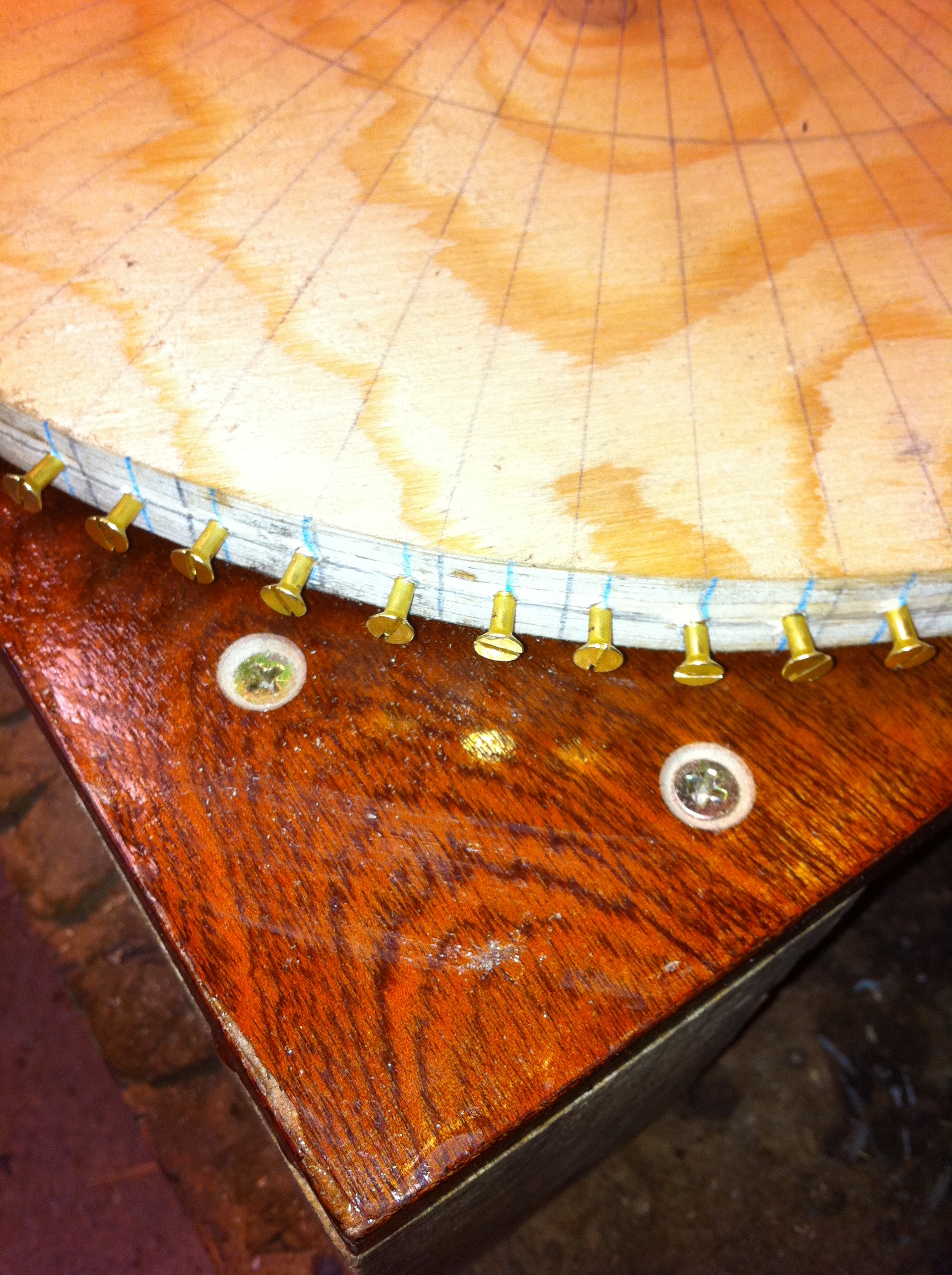
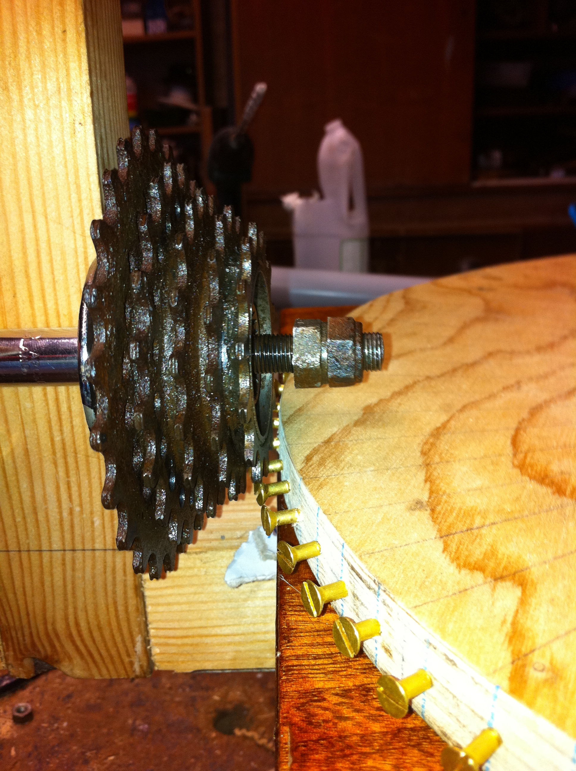
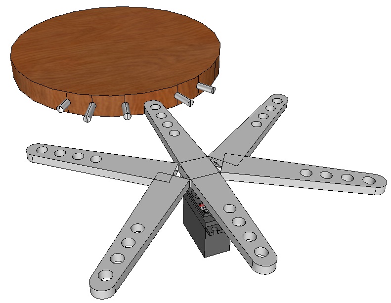
the servo motor will have a rotating arm at the end which can rotate through 360 degrees, it has 6 arms on it so each arm is 60 degrees apart.

what i need is a program for the PIC that will make the servo motor rotate one arm or 60 degrees every 11.5 mins

any help on this guys would be brilliant :smile:

many thanks in advance

Conal
 

Should be very easy, try writing it yourself.
If as you describe, it turns at a constant rate you can simply use an AC or DC motor and gear its speed down until it is slow enough. If you want to use a stepper motor, knowing the number of degrees rotation per step (from the motor data sheet) you can work out how long to wait before moving to the next step position. If you need to accurately control the speed, you need a feedback mechanism to let the PIC work out if it is going too fast or too slow. Unless you use the stepper method I think you will run into problems unless you gear the speed down considerably, trying to control the speed of a motor doing 0.0145 RPM would be very difficult!

Brian.
 

Hi Brian, thanks for your quick reply.

im not really trying to use any other components.

what i need is a program that will make the servo rotate once (60degrees)

then just stay stationary for 11-11.5 mins

then move onto the next stage

that is all it needs to do, continously.

would this be hard to write, I am completly new to this software and not really sure where to start.

many thanks

Conal
 

do you already have the servo? if so how is it controlled?
as a controller any microcontroller would do, if you are looking for a low cost development kit have a lok at microchip's microstick
**broken link removed**

it is self contained with on board programmer and has a header so you can attach it to your own breadboard. Compiler etc is free for academeic use.
One of the processors provided is a dsPIC33 which has a motor controller and quadrature encoder interface specifically designed for the type of application you are looking at
have a look at the various application notes
dsPIC33FJ64MC802
 

although the Microstick is a great tool, I think the solution to this problem is more hardware related than software.
Can you tell us more about the motor you plan to use, in particular the electrical needs and how fast it rotates. It would also be useful to know how accurate the positioning has to be and how quickly it has to move from one position to the next. Does it rotate continuously in one direction or does it have to 'reverse' back to a starting position periodically?

My line of thinking is that it may be easier to operate a sensor at 60 degree points around a circle and just turn the motor on until it is reached. For example, a magnet on one arm could operate a reed relay switch at each stop point and a simple NE555 timer could start it again every 11 minutes until the next point was reached. The cost would be very low, reliability very high and it wouldn't need any software!

Brian.
 

thanks for all your info so far guys, and brian if i could use a system that uses zero software that would be excellent as im a mechanical engineer and not really software, but as an engineer im trying my hand at everything + my tutor wants me to use this system i think

i think i can upload a picture to sho you what i need,

in the picture, you can see a round table, on the cicumference of this table there is 95 brass wood screws (this took along time)

the idea is that with the servo, i could place the first arm inbetween two screws, and after 11.5 mins the arm of the servo would rotate and the second arm would catch inbetween the next two screws.

i hope this gives you a better idea.

also the servo is not providing the drving force, the driving force come from an arrangment of bicycle chains and sprockets with a weight suspended from the top.

so essentially ther servo motor is there to stop the table from rotating to fast.

thanks again so far guys i hope this explanation and pictures makes things a bit clearer.

many thanks in advance


Conal.

---------- Post added at 23:59 ---------- Previous post was at 23:58 ----------

[

[/IMG]
 
Last edited by a moderator:

I think this possible with some electronics. 555 timer for time trigger and for motor you need to be more clear what you are going to use and what is the supply to the motors. If you are using AC motor and use your regular AC supply then I think there ample number of speed controls that can be used. If you are using DC motor then use you have give a battery supply. Either way you can do it the logic here is speed and time.

Thankyou
 

If I understand, what you have described is a called an "escape mechanism", basically the way a pendulum clock works. In a clock, a spring provides the force to continuously rotate a wheel and the pendulum periodically releases a brake to allow the wheel to move for only a short time each time time it swings.

I'm not sure where the 60 degrees angle come into this, if there are 95 screws and you want to move to the next screw position each time, the angle is 3.79 degrees. Are you saying the brake mechanism has arms at 60 degrees and each arm should position between the next pair of screws? If that is the case, you have a further potential problem because there is no speed regulation on the rotating table. The speed you would have to react with the arms to catch the next screw would be dependent on how fast the screws passed by.

Can you draw a diagram of how the arms interact with the table. The optimum method of controlling the arms depends very much on the mechanical design. I think in a real World situation it would be more normal to use a single electrically operated latch and an either a photo-sensor or reluctance sensor to control the table rotation, it would remove much of the mechanism and allow it to synchronize at a wide range of speeds.

Brian.
 

thanks again for the replies guys,

brian

yes you are correct in saying that the brake arms are seperated by 60 degree there are 6 arms therefore one servo motor rotation = 360 degrees, one arm will be placed inbetween the screws, and when 11.5 mins is up the servo will rotate by 1 arm = 60 degrees

as you say there are 95 screws so 95 / 6 = 15.6 or really 16 complete rotations of the servo motor.

as for the other probelm (speed of the table turning), the turn table is mounted on a lazy susan bearing, the distance between the fixed base and turntable is 6mm i have placed small rubber balls inbetween this gap to reduce the speed of the turntable.

Can the servo not be directly directly connected to the PIC and both run off the same power source, i also have an RS232 board to test it on.

any ideas on any code for this problem?

i will do a solid edge drawing and upload asap.
 

the idea is that with the servo, i could place the first arm inbetween two screws, and after 11.5 mins the arm of the servo would rotate and the second arm would catch inbetween the next two screws.

Will the round table rotates? Will the arms move fordward towards the round table like changing the gear. What is the mechanism to move the arms forward.

Thankyou


this is just a really rough design, each arm 60 degrees apart inbetween two scres, every 11.5 minutes arm rotates, and

NEW arm will then be in between two new screws.
 
Last edited by a moderator:

ok Got it, Thanks so as the arm moves it will move the round table, right? Ok let me try a timer generator using 555 and simulate it if it works I will post here the full schematics.

Thankyou
 

thanks prmurthy thats great news :-D

that was just a quick sketch in google sketch (witch actually turns out is some piece of kit)

Conal
 

Hi Here the schematic and some simulation photos.

Please try different options of RV1 and RV2 for various timings. The larger the capacitor C1 the more time of on/off.

test.jpg
View attachment test.PDF


Any comments, errors, suggestions most welcome.

Thankyou


Note : The time of On is important so you have set accordingly RV1 and RV2.
 

thanks for the quick reply prmurthy,

so this essentially is a time delay circuit, could I make this ciruict and plug it directly in the servo motor that i have?

without the need of a PIC

thanks

Conal
 

This if for AC motor. For servo I need to check. Can you please provide some specs of the servo.

Thankyou

---------- Post added at 16:47 ---------- Previous post was at 16:39 ----------

why don't you try with AC motor ??
 

Type of bearing Plain bearing
Dimensions (L x W x H) 41 x 20 x 42 mm
Connector system JR
Manuf. Part No. RS 2 JR
Drive Plastic
Servo-technology Analogue Servo
Servo type Standard Servo
Stroke time at 4.8 V 0,19 / 0,17 s
Torque at 4.8 V 32 / 35 Ncm
 

No this won't work with this shcematics. This is 3 wire PWM servo. PWM is mandatory for this motor.

Try something DC motor if your load on the motor is less. If you use DC motor then replace Live and Netural with Live = + and Netural = -.

Thankyou

PS: Sorry the IC u208 will not support DC motors

---------- Post added at 18:19 ---------- Previous post was at 18:18 ----------

DC control will change.This schematic will not work with DC voltages.

Thankyou
 

ohh damn that, thanks for your help anyway pr, much appreciated.

i think i will still go ahead with the servo controlled by a PIC,

but i dont really know where to start with the programming.

anyone else any ideas or help would be greatly appreciated

many thanks in advance

Conal
 

Status
Not open for further replies.

Similar threads

Part and Inventory Search

Welcome to EDABoard.com

Sponsor

Back
Top