Continue to Site

Welcome to EDAboard.com

Welcome to our site! EDAboard.com is an international Electronics Discussion Forum focused on EDA software, circuits, schematics, books, theory, papers, asic, pld, 8051, DSP, Network, RF, Analog Design, PCB, Service Manuals... and a whole lot more! To participate you need to register. Registration is free. Click here to register now.

High power attenuator

Status
Not open for further replies.

pisoiu

Advanced Member level 3
Joined
Dec 31, 2002
Messages
750
Helped
43
Reputation
86
Reaction score
21
Trophy points
1,298
Location
Romania
Activity points
7,883
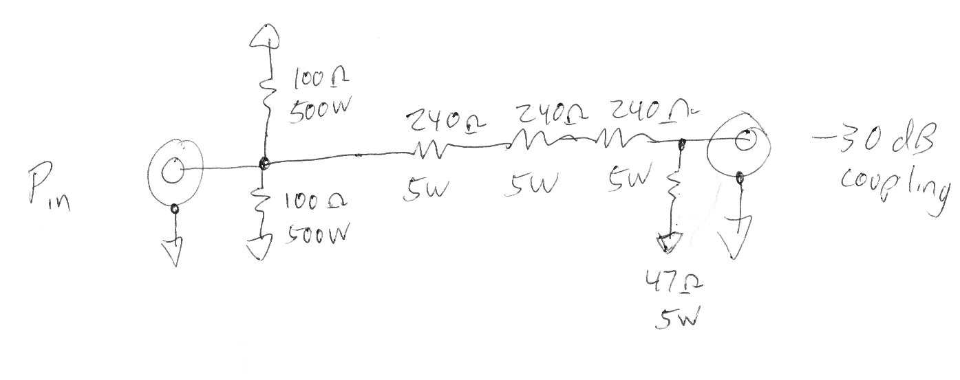
I need to make some tests with RF amplifiers up to 100 mhz and 1kw. I have some troubles finding a suitable attenuator/dummy load at this powers, with a reasonable price. I need around 40db attenuation for attenuator. Could it be done with two resistors like RF500BA15A (johanson mfg) mounted in paralel used as first resistor in a pi attenuator?

Regards,
/pisoiu
 

I use a Bird 1000-WAFFN-40 40dB attenuator from Bird for high power stuff.

These are expensive but they consist of a series of attenuators that slowly increase in size. Therefore you have to always feed the 1kW in at the correct end to stop it overheating LOL
The reason I mention how the Bird model is constructed is that I believe you could use the same strategy with a simply made design with low cost high power resistors if you are just at 100MHz.

Eg a series of 0.5dB attenuators then some 1dB then 2dB right up to 10dB until you have 40dB.
You would need to fit it on a huge black heatsink and blow it with a fan if you wanted to run it for long periods.
 
yes but u have to fix the mismatch at the common port
also the value of the resistor should be 100 Ohm...

OR

U can make wilkinson PCB and put both of them...

i prefer second option i did it in higher freq, i dont know what u lower freq...

David
 
Thanks. Of course, proper cooling will be added. The attenuators such as bird is nice stuff but I assume is quite expensive. For the moment I just want to do some high power experiments with ham amplifiers and I don't want to spend too much money. I just wanted to know if RF resistors such as that one indicated will do the job dissipating all the power and maintaining a good adaptation with the amplifier (two 100 ohm in parallel).
 

The "attenuator" is just a port to get a signal back for inspection? 100 Mhz is not such a high frequency, I would use a 50 ohm load with a tap of which is a 500 ohm resistor connected to the input line and the test port with a 50 ohm resistor terminating the test port. So the test port has a reasonable match (use a 55 ohm if you can find one).
Frank
 
  • Like
Reactions: pisoiu

    pisoiu

    Points: 2
    Helpful Answer Positive Rating
he dont want to use 50 ohm dummy load too much expensive
 

Many years ago there was a nice dummy load design described in QST magazine.
It was a water-cooled resistor power divider; I think it can work at 100 MHz, and you can use water-tap flowing water to remove your 1 kW.
 

Yes, I need an output to fed a VNA. I've seen such a resistor used in a dummy load here Build a RF Dummy Load . Hopefully I will manage to make a pi attenuator, first element being one such resistor 50 ohm or two 100 ohm in parallel.
 

Let me ask my question in this thread. In an rf power amplifier, reflected power may damage the output stage unless we terminate it appropriately. Is there a common precaution to prevent this damage in case of wrong termination(when it is left open for ex.)? I mean hardware precautions like a limiter! Thanks.
 

At microwaves we use isolators, but at 100 MHz and your 1 kW, this is not an option.

There are simple directional couplers with detectors available that due to their directivity indicate the forward and reflected power in a coax line. I would use this simple and low-cost device to control the RF power from your transmitter to a load. If the reverse detector exceeds output voltage, it can trigger the RF output inhibit quite fast.

Radio-amateur versions have been described and used for many years, e.g. in ARRL Amateur radio handbook and elsewhere. At 100 MHz and 1 kW, the cost may be < $10, only calibration would add more. The response can be several milliseconds, so any heavy mismatch will be handled safely for expensive power transistors of your transmitter.
 

Broadcast UHF transmitters have a reverse power detection circuit set to 5% of the forward power, this mutes the drive so that there is no power output and in addition trips the supplied to the PA so some one will take notice of the problem!!
Frank
 
  • Like
Reactions: ferdem

    ferdem

    Points: 2
    Helpful Answer Positive Rating
I would first look on ebay to try to buy something.

If I could not and had to make something, I would take two of those 500 watt beo resistors and connect them in parallel as a 50 ohm load. I would mount them on a rectangular copper pipe, and run water cooling at a high rate (like a garden hose running full on) to keep them cool. I would then capacitively sample, with a small 1000v ceramic chip cap, some of the power being dumped in the 50 ohm high power load. Select the capacitor for around -20 dB of coupling. After that, I would place a coaxial 1 watt pads, say 1 dB, 3 dB, and two 10 dB pads. Then I would carefully turn on the transmitter, slowly ramp up the transmit power, and see what came out the end coax pad.


You could try this. Use big connector at the input to keep from arcing. Lots of water cooling or a gigundo heatsink/fan.

Rich
 
Last edited by a moderator:
Status
Not open for further replies.

Part and Inventory Search

Welcome to EDABoard.com

Sponsor

Back
Top