Continue to Site

Welcome to EDAboard.com

Welcome to our site! EDAboard.com is an international Electronics Discussion Forum focused on EDA software, circuits, schematics, books, theory, papers, asic, pld, 8051, DSP, Network, RF, Analog Design, PCB, Service Manuals... and a whole lot more! To participate you need to register. Registration is free. Click here to register now.

Ongoing problems with X2 mains capacitors in triac switch application

Status
Not open for further replies.

userx2

Full Member level 3
Joined
Sep 19, 2008
Messages
158
Helped
2
Reputation
4
Reaction score
2
Trophy points
1,298
Activity points
2,931
Hello

I am a design engineer and I have a problem with X2 as well as Y2 film capacitors failing in one of my products.
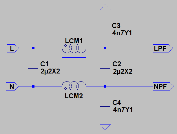
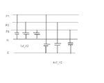
This is a 3 phase application and the capacitors are connected from from each phase to neutral (X2) and from each phase to earth (Y2).

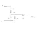
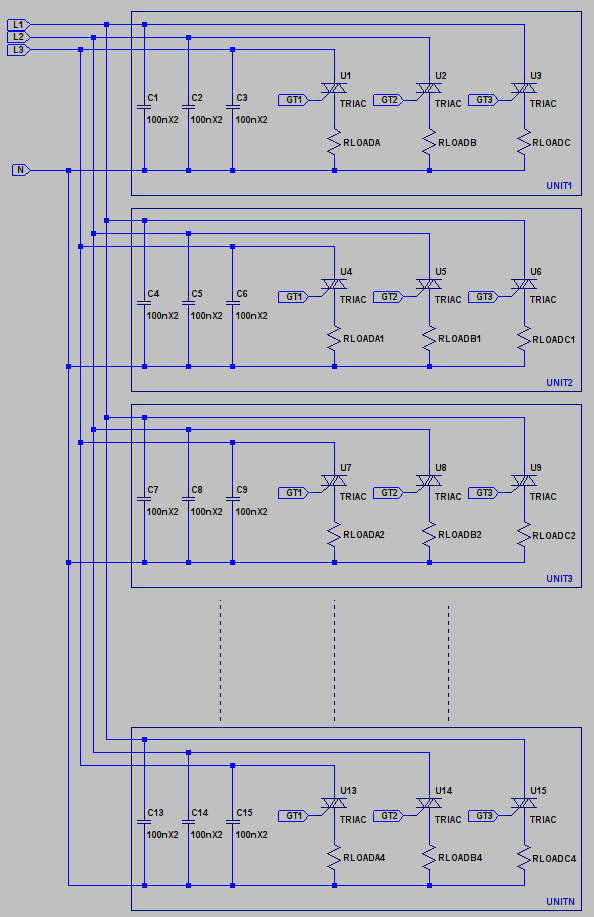
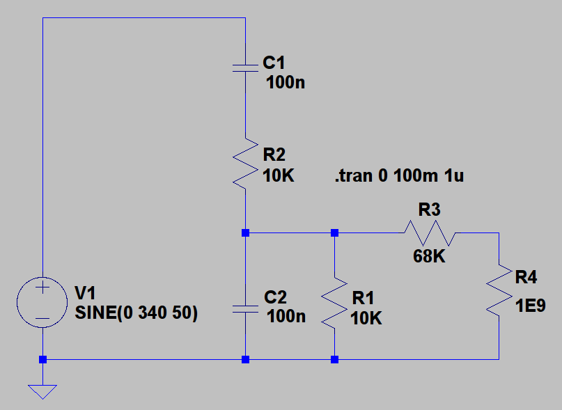
There are also other X2 capacitors used in the circuit, some on a filter application with series resistors.

The unit itself does triac switching (dimming).

Long story short, the capacitors fail after about 6 month in the field. The capacitance decreases to almost nothing. a 100nF capacitor will maybe have 2.2nF left when it get back here.

The same happens with the Y2 caps.

I have disected some of the capacitors and found that the silver foil inside them has gone transparant, compared to a new unused one.

One explanation is that they are sitting there, experiencing billions of transients and self healing billions of times until there is nothing left of the foil.

Fair enough but after exhaustive tries and testing, I have not been able to measure any such transients here in the lab and these units are shipped to all different parts of the country. What is worse, is that the Y2 caps do the same thing and they are much more resilient than X2s.
These are asian capacitors as we ar enot able to get others dues to long lead times of 50+ weeks (!!)

Has anyone in the professional world of power electronics out there experienced similar problems and what was the cause / remedy?


Any help / ideas will be greatly appreciated!

Kind regards
 

Since you mention that this is a 3 phase Supply I would imagine that you are dealing with a high power circuit. Would it be possible to see a circuit diagram?

I am used to dealing with Switch Mode Power Supplies, single phase up to 500W, and might use an input filter similar to this,


I'm not experienced with 3-phase supplies so might only guess what the equivalent might be for your application. However you will see I am using 2u2 devices for the X2 locations. This is required in order to achieve the required EMC specifications. I use 4n7 for the Y1 locations to remain within earth leakage requirements.

Those 2u2 devices are 22 times larger than your 100nF devices and I might imagine that they are living in a much 'cleaner' environment. Many capacitors will or should have details about their dV/dT ratings.

Naturally they should be rated to deal with the basic AC mains voltage applied to them but if your circuit is in some way adding to this then that should be taken into account as well. I think that might be likely with Triac based loads.

You say you have measured no 'transients' in your circuit but you may be referring to 'over-voltage' stresses rather than dV/dT. Over-voltage may cause 'punch through' but dV/dT may well caused localised heating and loss of metallisation.

It will be a regenerating effect since as your capacitance goes down with the same load conditions on it the dV/dT will increase and so will the wearing away of what is left.

Of course I might be wrong but rather than looking for transient overvoltage I would suggest that you look at what sort of dV/dT is being applied across the devices and check if that is within limits as specified on the data sheet.

Genome.
 
Last edited:

Hello

Thank you for the reply!

I have attached a rough sketch of the input circuit.

The mains voltage is 240V and the unit can draw 40A or 10kW per phase.
The caps are rated at 275VAC.
Further down, there are also MOVs, rated at 265VAC.

I do not see the failures consistenly across all the capacitors.
In some of the samples I have, only those on a single phase are low and in others, none anbd yet in others, all of them.


I am honestly stumped by the capacitor failures. Something happens to them in the field that I cannot explain yet.

There is an off chance that these could be poor quality capacitors as well but I am not even able to prove or prove that.
 

Attachments

  • X2 capacitors.JPG
    X2 capacitors.JPG
    15.4 KB · Views: 182

I have to say Sir 'That is Serious Power'. 10kW/Phase makes 30kW and about 42A per phase. If I were a capacitor I'd run away and hide if you wished to buy me...

Does the circuit work in the 'lab' without the X2 and Y2 capacitors in place?

I'm guessing that if you are getting 'field returns' as a result of those capacitors failing then something else goes wrong in the circuit as a result which is fairly obvious to the end user.

Otherwise there is the possibility that things have been connected incorrectly or the 'local' supply, any particular phase or perhaps neutral, is not capable of supplying your circuit or your circuit places an unbalance on the phases that drives neutral sufficiently out of specification that the differential voltage starts to kill the capacitors...

I'm just 'floating' ideas.

Genome
 

Yes, that's a very serious voltage & current and i do not think capacitors are efficient in handling such power on a long term basis.
 

Hello all,

Ahh, it isn't really that much power :cool:

It is also the maximum power and depending on the loads and setting, it wil vary greatly.

The capacitors are for EMC / EMI filtering and they should have nothing to do the how much power is consumed.
The circuit works just the same with these failed or not and nobody is the wiser if they fail.

However, just a little further down, on each phase in the circuit, there are 2 more X2 caps used in a sort of voltage divider circuit, whch supplies the input to an op amp circuit, which in turn is a lower pass filter. These fail in the same way and they cause a serious phase shift in the zero crossing generator circuit. That is how I found this problem.

I am still none the wiser here.

Kind regards
 

I would guess that the caps are failing depending where they are used in relationship to the local mains switching centre and how its done. The comment about the power rating is true, at this power level you have a few milliohms of resistance between the caps and a huge transformer and a few more to a switching centre, there is nothing that reduces the high frequency current component unlike a filter that is used in a lab with local 10A wiring, then breakers then 100A wiring then more breakers. . . Stuff a bit of inductance in series with the three phase leads. :)
Frank
 

I'm inclined to support Genomerics' views on the selection of the caps by parameter. (I'm no stranger to receiving production equipment with SMPS failures for assesment and repair).

I'll try to reply in more detail over the next few days when the opportunity arises. But in the meantime, I must say that in my many years of work with 3-phase supplies, I ALWAYS assume that each phase has the POTENTIAL to deliver the full voltage of any delta circuit PLUS any back-EMF to any appliance. (The regular appearance of units with SMPS failures on our workbench with only Cap failures is now dealt with by someone who simply replaces caps rather than someone with electronic experience and qualification).
I'm sure you already know this, but for clarity lets be quite sure - any current drawn from any phase (of a 3-phase supply) flows between its live phase and the loads (whatever they might be) on the other two phases. It does NOT flow between its live phase and earth - earth is virtual, at which point it becomes known as 'neutral'.
(if this wasn't true, commercial 3-phase supplies would have neutral conductors which were 3 times the diameter of the phase conductors. They don't).
The consequence of this is that you should be considering the dynamic and phase-shifted 'load factor' across all the phases of your supply, all their back EMF, all other capacitive and reactive elements across 'your' phase AND across the other 2 phases, and the variable state of the virtual earth called 'neutral'.
This provides a picture of a very hostile and high voltage environment, before we start to add the impact of supply-line spikes (lightning, generator switching or faults) and user faults (trippping out a whole phase and sending all current and EMF through 'your' phase).
With any luck, that should point you towards one or more areas of weakness, which I guess, is what you're looking for.

You're not in a position I'd want to be in, but one day, I might be! - Good luck !
 
Last edited:
I have not been able to measure any such transients here in the lab
I understand, that dV/dt in operation is considerably below the specified capacitor rating. But dV/dt would also depend on the grid impedance and (you didn't tell the application) also on different loads, that may be connected in the local installation? So can you be sure by design, that the circuit can't generate higher dV/dt under unfavorable conditions?

Grid-side overvoltages would be possible as well, normally, X and Y capacitors are designed to keep them. But special power distribution systems, e.g. implementing harmonic filtering of the plants power supply towards the outer world may cause strange waveforms on the inside. Do you observe the problem everywhere or at a single place?
 

Hello all and thanks again for the help.

Yes, it is a bad position to be in as a lot is at stake here.
Needless to say, the equipment we make, pays the bills 8O

Let me clarify some more:
The loads on the outputs of the unit connect from each phase to Neutral.
The unit can still function with only 1, 2 phases active.
Each load can be varied seperately so there is no hope of ever balancing the loads across 3 phases.
The current ALL goes to Neutral and yes, the Neutral wiring is heavier than the phase wiring.

A lot of the units (as many as 50 of them) are mounted into a single large installation, all running from a mains distribution cabinet with some serious size wiring inside it. In this scenario, many have failed 2 or even 3 times already but also, many others haven't.

Of course, they may well see overvoltages as well as transients while operating 24hours a day . in the field. I have no way to veryify it though.

Assuming they do, then what can I do?

I have done my utmost to simulate the failures by creating transients here in the lab, under full load and others, by switching in contactors, tripping breakers, arcing etc etc. Nothing happened.

Also, the top cap in the circuit shown here (sits further down in the circuit) also goes low val really often. Teh bottom one not so much.


As mentioned, I am stumped and mostly out of ideas.

I am seriously considering moving to X1 capacitors instead but until I actually understand the exact mode of failure, this could be another expensive flash in the pan.
X1 caps are bigger and do not simply fit onto our boards

There are also ceramic capacitors and I am wondering if those might be a better alternative?


Kind regards
 

Attachments

  • DCP2.JPG
    DCP2.JPG
    10.7 KB · Views: 189
I don't understand, how the shown circuit with rather high-ohmic resistors should be related to EMI filtering and your said application? If you connect it to mains voltage, the capacitor will only "see" the fundamental and partly low harmonics, so theres's no chance to overload it by transients. Only a serious AC or DC overvoltage (>400 V AC, > 800V DC) could damage it.
 

If you are planning to make a EMI/RFI filter for critical applications then along with capacitors require inductors too, as an example (single phase)

**broken link removed**

C1=0.1 uF (the X capacitor)
C2=4700 pF (the Y capacitors)
L1=22 mH common-mode choke
R1=1M ohm bleeder resistor

Some equipment requires an inductor or ferrite on the ground as a defense against incoming common-mode noise. A few filter modules do have ground inductors.
 
Hi again

From your description so far it looks like you have something like this?


Separate units placed in an installation where there may be up to 50 installed. The load for the installation is your figure of 10KW/Phase 30KW total with each unit rated at 600W total or 200W per phase. If that were so then, in isolation, 100nF X2 capacitors in each unit would not seem unreasonable.

You mentioned 'dimming' and if the above figures are correct then I would assume you are you are dealing with some sort of theatre lighting system...? As such you might/will not have much control over which loads are active so, as you suggest, balancing the loads on each phase will not necessarily be feasible.

I'd also guess that you are unable to test a 'complete' system in the 'lab' but are restricted to a single or limited number of units. Since the field failures take six months then you can't really sit around in the lab waiting for something to happen...

So, assuming the above is correct.

In isolation things might be OK. With a single unit is it possible to measure the current in the X2 capacitors? I should hunt out a data sheet but in as much as they have dV/dT ratings they may also have dI/dT ratings. If you have a current probe then good otherwise put a low value, low inductance resistor, 100mR ?, in series with one and measure across it to see if there might be problems in that respect.

As you say since you are unable to balance phase currents then as suggested you might be driving neutral via one phase such that the other phases suffer overvoltage. They only real way of testing that would be on a complete system so I guess you would have to go and play with one unless you can install some sort of monitor.

Load up a single phase to its maximum and measure the relative voltages to see if there is an overvoltage condition on the other phases.

One final thing to look at is whether the units that fail are always in the same or similar locations within within the installation. I would guess that this is some form of standard install and wiring loom within the cabinet containing the units....

As I have drawn my picture then they are connected as a 'bus' to the main input so in operation you might expect 'UNITN' to experience a reduced input voltage and be 'happy' whereas 'UNIT1' directly at the input would experience the full supply. That may or may not be a problem although if there is some concept of transients during 'load dump' or otherwise it will be subjected to worse case conditions.

I'm not sure it would exist but there may also be a scenario as a result of the way things are wired that whilst the 100n capacitors are fine for a single unit there may be some way whereby when things get connected those capacitors are effectively shared and one or a number of units may be loaded 'preferentially' stressing its/their devices more than you might have expected giving rise to early failures.

Regarding your zero cross-detector. It does seem strange that you would see failures here given the current is effectively limited by the 10K resistor unless, once again you are seeing some form of overvoltage. The upper capacitor does effectively see the full line voltage.

I would not be certain but in this particular part of the circuit you do not need to use X or Y rated capacitors. They are designated as such because they are expected to be connected directly across the supply, X, LN LL or, Y, LE. In the network you have that is no longer the case.

Here is a quick model of that part,


I don't now what sort of op-amp circuit you have connected to the output on the end of the 68K resistor but some figures are,

C1 273V peak 194V RMS
C2 82V peak 56V RMS
R2 85V peak 59V RMS 0.366W dissipation
R1 82V peak 56V RMS 0.334W dissipation

As given the circuit does seem to introduce what might be unwanted phase shifts to the signal being measured. I would not know if that is an issue in your circuit. Otherwise given it is presenting its output to an op-amp then I might expect that you would be able to scale the components for lower power dissipation and replace the capacitors with, perhaps, normal 4n7 1kV rated ceramic devices.

Genome.

---------- Post added at 12:58 ---------- Previous post was at 11:24 ----------

One thing that occurs having seen and been reminded by Prince213's post is that due to the location of the X2 capacitors on the line side of the common mode choke they are, to some degree, protected from load current transients by the differential inductance of the common mode choke. That 'parasitic' is used to control differential mode noise as well.

In your case, if I am right that you are using these units to control incandescent lamps, then you may have to take into account the 'cold' resistance of those lamps. That would presume the units are required to do some 'high speed' flashy light show sort of thing. Picking figures out of my hat then say your 200W lamp draws about 0.8Amps when fully on. If its cold resistance is, guess, 50 times less and you just switch it directly at the right/wrong point in the line voltage then that would be 40Amps which may well hurt the capacitor.

It may be possible to adjust something within your control circuits to avoid or perhaps reduce such effects.

Genome.
 
try using series resistors in line with the caps. (~39E)
 
  • Like
Reactions: userx2

    userx2

    Points: 2
    Helpful Answer Positive Rating
I'm impressed by Genome's analysis and hope you found that helpful. I'd like to add two more factors which I'm sure will place considerable stress on the Caps.

Firstly, my earlier post about the role of the neutral connection might not have been clear enough.
It is generally safe to assume that all currents flow between the phases and neutral (and you have emphasised this by referring to the higher capacity of the neutral cable). Sadly, this is only useful up to a point; sure, your test equipment and bench supply will always take measurements relative to neutral, but this is only a 'virtual' reference. The current path is between the phases, and out in the field (with hire companies and in fixed installations) there can be relatively little current flowing in the neutral. Your component selection should allow for full phase-phase voltages, particularly for all high frequency calculations.
To illustrate: when a capacitor from Phase to Neutral offers a path for a high frequency pulse, the actual path will be from that Phase via the 'virtual' neutral, through the identical paths of the corresponding capacitors to the other 2 phases. If that was a positive voltage pulse on the Phase, then that must be added to the full phase-phase voltage. Component selection must be rated for your percentage estimate of over-voltage transients based on the phase-phase voltage.
In Genomic's diagram, please picture the groups of 3 caps simply being in series between each combination of phases, diverting any peaks on one phase onto the others. (A star arrangement with its neutral disconnected).

Secondly, thyristor/triac switching is well known for introducing high frequency "spikes" and I'm sure you are no stranger to dealing with these. However, in a real-world application, a dimmer rack may have a full lighting rig at some intermediate stage (eg each cycle is 'chopped' near the highest point in the voltage cycle). However, not each dimmer will necessarily 'chop' at precisely the same point in the voltage cycle. (Its likely to be a rapid sequence of channels 'chopping' in quick succession near to a voltage peak). This very sharply decreases the load on the phase during its high voltage part-cycle, which in turn, and equally sharply, shifts the voltage on the 'virtual neutral' towards the other 2 phases (though as you will be measuring everything relative to 'neutral', you might want to say this produces a sharp voltage drop on the other 2 phases, repeated during each cycle by every other dimmer on that phase).

Add to this that some lanterns may have reactive elements, which, when their supply is 'chopped', will introduce substantial pulses onto the other 2 phases.

Hopefully this approach will illustrate that the dimming of all channels in a well loaded rack produces intense and powerful voltage changes across its own supply phases. The current ratings you will know from your equipment's nominal specification, but again, I urge you to think about the large changes in current during a single voltage cycle when the full load is dimmed to, say, half power. (Though in my experience, the most agressive spikes occur at much lower lighting levels, where the waveform is a rapidly rising edge followed by an instantaneous fall and all the ringing artefacts that come with the loss of connection to the supply).

So what advice do I have? Sadly, I'm not sure, however I would suggest using X1 and Y1 capacitors instead of X2 and Y2 (to anticipate higher voltages), place additional capacitors close to each thyristor/triac, place small resistances in series with those caps (as proposed by carlmbecker) rather than small resistances in series with the (uprated) capacitors in the original positions.

I am not persuaded that the introduction of inductors/coils in the incoming supplies will help - you need the lowest impedance possible in these supplies, particularly at high frequencies. It is surely the capability of the low source impedance of the supply phases to absorb high frequency energy and to maintain the supply voltage that will save your capacitors?

I would also be interested to learn if the failing units are being returned from venues in large cities with high capacity / low impedance power supplies or those with poorer supplies further from the transformers and if any clients have been using them with reactive lanterns or on outdoor shows powered from generating sets.
 
Last edited by a moderator:
  • Like
Reactions: userx2

    userx2

    Points: 2
    Helpful Answer Positive Rating
Hello

I must say, I am really happy to have found you guys here on this forum.
It was just a shot in the dark because I had noone to discuss with here.
Nobody knows much about these things.
Therefore, I greatly appreciate all your input. It helps me greatly, to get out of the thinki9ng lull and get this sorted.

Genome is correct in all instances. Loads can typically incadescent 2kW.
A cold filament can draw as much as 20kW if suddenly turned on..
The units I design are a little more advanced in that they will take care of cold filaments by ramping the currunt slowly and there are also other features like lamp preheat etc etc.

In addition, there is a Neutral / Earth voltage detector. It will detect a fault if the neutral voltage rises away from the Chassis / Earth voltage. In theroy, it should detect the case of the drifting neutral due to unbalaced loads.

I have seen the arer case, where the neutral has drifted due to a cable failure or bad conenction, the unit and loads connected have not survived with very obvious failures.

Also, the channels each have additional capacitors as well as chokes, to slow the risetime of the load voltage / current for EMC reasons.

I must also mention that I have MOVs across the phase / neutral and series PTCs (not in the main load loop) as well. They should in theory clamp all overvaltages, especially those that go to the 2 capacitor input circuit mentioned.
Yet, the top cap goes faulty in almost all instances tested. That is all part of the puzzle.

Sorry about the slow / vague circuits.:oops:


As for the series resistance for the caps you folks suggest:
What has so far stopped me from tryiong this is the fact that the top cap with the 10k series resistance goes faulty as well.

In fact, that top cap going faulty, is the real killer of all theories for me.

I will print you responces and study them today :lol:

Regards
 

Attachments

  • DCP3.JPG
    DCP3.JPG
    12.7 KB · Views: 176

The MOV point is interesting. In my opinion, you have already sorted out dV/dt overrating by observing failure in the RC zero crossing divider circuit. Assuming the MOV are still intact, you can also exlude low frequency/statical overvoltage. So what's left:
- incredible bad capacitor quality
- some unusual kind of incorrect device processing during manufacturing (chemicals, temperature, ...?)
 
  • Like
Reactions: userx2

    userx2

    Points: 2
    Helpful Answer Positive Rating
The MOV point is interesting. In my opinion, you have already sorted out dV/dt overrating by observing failure in the RC zero crossing divider circuit. Assuming the MOV are still intact, you can also exlude low frequency/statical overvoltage. So what's left:
- incredible bad capacitor quality
- some unusual kind of incorrect device processing during manufacturing (chemicals, temperature, ...?)

Hi,
You are now getting to the exact point where I currently am. :cry::cry:


The MOVs have not gone faulty in these specific cases but that capacitor has.

Here is my thinking further to this
1) I also assume bad capacitors but wait.... The bottom cap in the circuit NEVER fails and nor do some others in the circuit elswere. The capacitor manufacturer is not helpful at this stage although they did get faulty samples back from me.
There are currently caps of 2 asian manufacturers. Both fail.
Hence my question if anyone else here has maybe come across this same problem.

2) I am currently ruling out incorrect processing because after the initial failure, we carefully handsolder the replacement parts. They then may fail again after some time.

I would love to be able to test the capacitor quality / resilience but have found no reference as to how this could be done in a simple way.


Kind regards


---------- Post added at 00:37 ---------- Previous post was at 00:26 ----------

Hello again.

Genome, here is the capacitor data (from datasheet)
There is no dI/dt given.

Rated V = 275VAC
Dielectric Strength = 1183VDC for 1 minute and 2000VDC for 1 second
Maximum Oulse rise time dV/dt 120V/us

Also, the max loads I mentioned, are per unit and per phase. This means that 50 such units can theoretically draw ~2000A from each phase in the installation.
 
Last edited:

Hmmm, yes I also take the point about failure in the divider.

You have said that, apart from that particular location which is the one that brought things to your attention, the other capacitors are just for EMC purposes and the units will function even if those particular devices do fail. Given there are multiple units within each installation then do they not effectively 'share' those capacitors such that even if some do fail the EMC 'protection' is still in place because there will still be functioning devices in place?

Effectively, in terms of go/no-go, the 'critical' thing is the divider so if you could sort out the reliability in that location the rest would become a matter of 'scheduled maintenance'. What I'm getting at is that when your divider fails the customer experiences downtime or is otherwise inconvenienced and you get called out to fix things. Otherwise they are 'none the wiser' and 'happy'.

Then, until you know what the 'real' problem is or otherwise, it is just a yearly visit from one of your technicians to check over the units and replace suspect capacitors or whole units with the duff ones being returned for refurbishing. When you manage to source different capacitors you can try exchanging them as and when to see if reliability is improved.

If that sounds good then all you need to do is raise the impedance at the node where the op-amp is attached and rescale the zero-cross circuit components in order to use lower value high voltage disc ceramics, I'm sure they go up to 10kV and more but you need not get carried away. I assume it is anyway but just make sure the op-amp input is suitably protected.

It's not a complete 'solution' but at least it keeps things running and gets people out of your hair.

Genome.
 

One additional comment on the zero crossing divider. A dV/dt of 100V/µs calculates to 10 A with 0.1 µF. At least two orders of magnitude above the operation conditions in this circuit. It really doesn't sound like an electrical overload problem. Applied voltage may still play a role in the capacitor "disintegration" process, e.g. by causing electromigration together with inappropriate materials used for it's production.

When you manage to source different capacitors you can try exchanging them as and when to see if reliability is improved.
Yes.
 

Status
Not open for further replies.

Part and Inventory Search

Welcome to EDABoard.com

Sponsor

Back
Top