Continue to Site

Welcome to EDAboard.com

Welcome to our site! EDAboard.com is an international Electronics Discussion Forum focused on EDA software, circuits, schematics, books, theory, papers, asic, pld, 8051, DSP, Network, RF, Analog Design, PCB, Service Manuals... and a whole lot more! To participate you need to register. Registration is free. Click here to register now.

Error : iteration limit reached for mixed sim

Status
Not open for further replies.

rdastyle

Newbie level 5
Joined
Nov 17, 2010
Messages
8
Helped
2
Reputation
4
Reaction score
2
Trophy points
1,283
Activity points
1,332
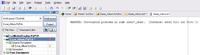
Error : iteration limit reached for mixed sim in ALTIUM DESIGNER

Hi everybody,

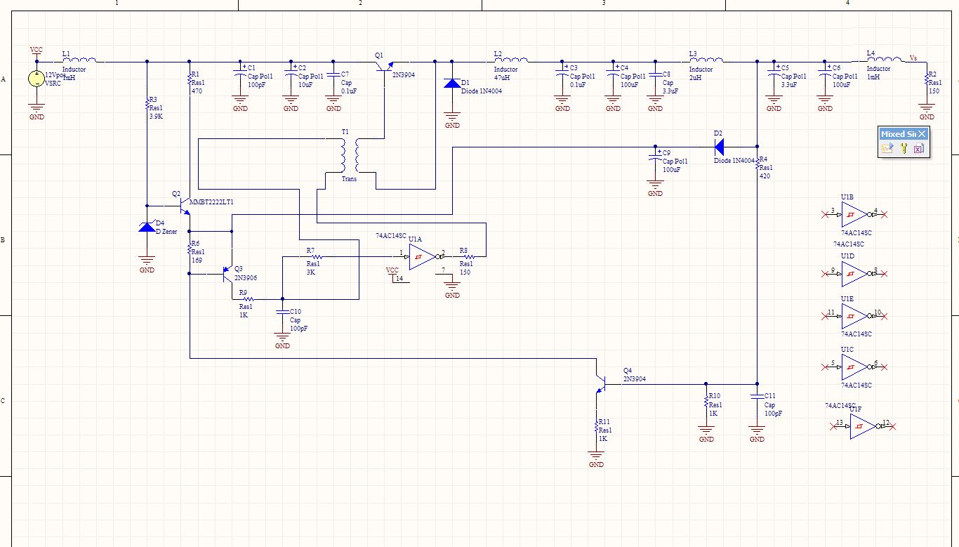
I'm working on a switch-mode power supply (" Alimentation à découpage " in French :wink:).
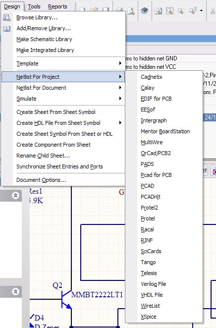
I'm using Altium Designer Summer 09 and I try to simulate it.

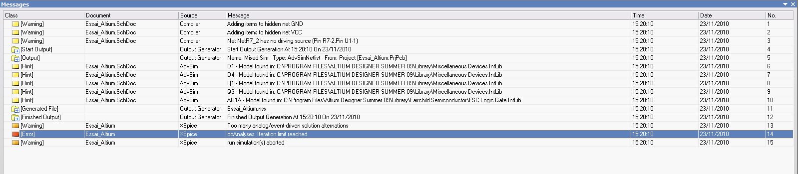
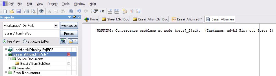
I've got a trouble with the element " 74AC14SC " which is a Schmitt Trigger Inverter.
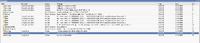
Without this element, the simulation does not produce error but when using it, it does.
I attached some pictures to show the situation.


--> Have you got an idea to solve my trouble ?

Thanks.
 

It is only a guess, but you have 5 floating Schmitt triggers on the right hand side - try deleting them or grounding their inputs.

Sometimes simulations fail because of something other than the device you just added. That can be tricky to find but inductors with no series resistance can cause a problem, particularly when they are in series with a voltage source and a capacitor with no series resistor.

If you could post the complete netlist including models then it could help. If I can run the netlist on my simulator I am used to trying to find convergence problems using its error information.

Keith.
 

Thanks for your answer.

I'm supposed to use the others 5 floating Schmitt triggers. Actually, I've tried to make it work with one trigger.

I just posted a folder in which you will find my schematic and the rest of the files.

The trigger is available in the " FSC Logic Gate " library (this library is included in Altium Designer Summer 09 and can be download at this adress : **broken link removed**).

Thanks.
 

Attachments

  • Folder.zip
    66 KB · Views: 87

I cannot help with the Altium files as I don't use Altium. I could probably do something with the netlist provided the libraries are included. The Altium libraries are not straight Spice files but in Altium format so I cannot even look at the Schmitt trigger model..

Keith.
 

Hi Keith,

I have the possibility to output several format thanks to Altium (see the picture).
19_1290594199.jpg


Which one do you want ?
 

I would have said Spice, Hspice or Pspice but those aren't any of the options. I think they are all netlists for PCB layout, with the possible exception of Xspice.

If you look in the project directory it will probably create a netlist (maybe a .net file). Another useful file may be the output or list file, usually .out/.lst extensions. They would normal contain the netlist, models and output data.

Keith.
 

Understood.

In the folder I just attached, you will find a .NET file.

Thanks.
 

Attachments

  • Project Outputs for Essai_Altium.zip
    111.6 KB · Views: 124

The nsx file is actually a Spice netlist. I have managed to run a transient analysis with it, but I had to do two things (other than sorting out syntax differences):

1. as I don't have your 74AC14 model I used a model I have,

even then I got the error message
Code:
*** ERROR *** Too many analog/event-driven solution iterations
This may be due to an unstable feedback loop e.g. an oscillator
Use an "Initial Condition" to break loop during DC bias calculation

so:

2. I simply selected "skip DC operating point" in my simulator.

I see you are trying to find the operating point. I think the simple answer is there isn't one. I suggest you run a transient analysis. If you have trouble getting it going then skip the DC operating point or add some initial conditions.

Keith.
 

Once again, thanks for your support.

I was already in Transcient analysis and I still get an error of Convergence :

" WARNING: Convergence problems at node (netr7_2$ad). (Instance: advb2 Pin: out Port: 1) "

It seems that the R7 resistor, which the output is linked to the input of the trigger which is connected in the shematic, gives me some trouble.
The shematic represents a circuit that has been tested and it works, but not optimized.
If you are using PSPICE, then I could try to solve my problem with this software because I got it and I made the schematic on it too. (Currently, I prefer using Altium because its very user-friendly but I agree PSPICE got hard knowledge in simulation)
 

I don't actually use Pspice but a few options to try if you are having convergence problems are:

.OPTIONS PIVREL=0.999

increase ABSTOL (using .OPTIONS)
increase VNTOL (using .OPTIONS)

You can try RELTOL, but it is not usually a great solver of problems (the default is usually 0.001 anyway).

Different simulators seem to be quite different at how well they handle and solve convergence problems.

Keith.
 

Ok Keith, I will try to enter these informations.
 

Status
Not open for further replies.

Part and Inventory Search

Welcome to EDABoard.com

Sponsor

Back
Top