joecla
Junior Member level 1
re: problem on inverter simulation
Hello everyone,
I'm in a dilemma of finishing my inverter design. I simulate this with a MULTISIM release 10 (student version) but can't get exact what I want with my design. May I request everyone those who are interested to simulate this design for me using MATLAB, PSIM and MULTISIM if possible.
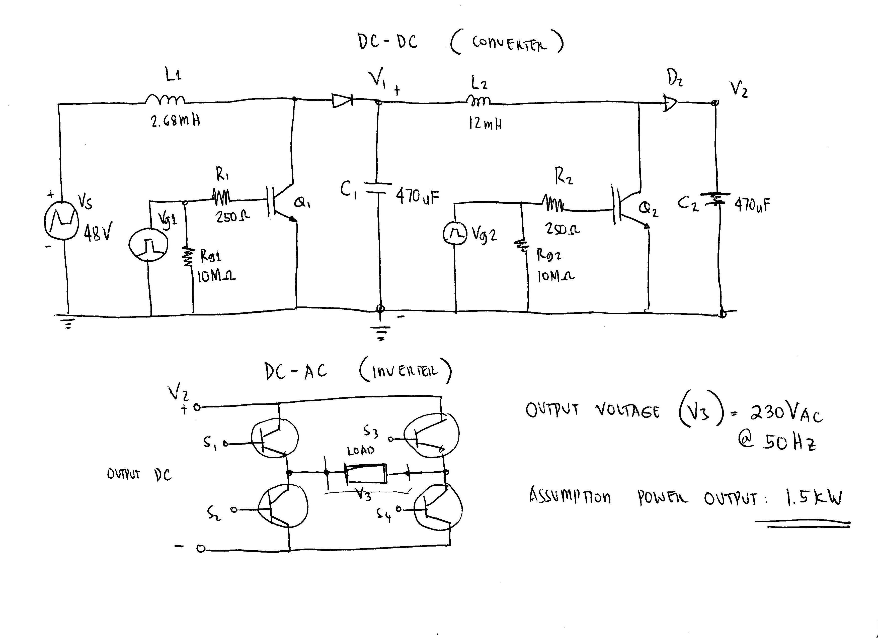
I don't know if the value of my components are exactly right. I also want to know the voltages of V1, V2. and how much voltage for the V2 as input to inverter to produce 230 Vac.
This is two stage DC-DC converter and then a DC - AC inverter design.
The specifications are:
Input 44 Vdc - 52 Vdc (nominal 48Vdc)
Output frequency 49 - 51 Hz (nominal 50Hz)
Output waveform Pure sine wave
Output voltage 220 / 230Vac
Output Power 1.5 kW
I decided to use the IGBT for the switching devices.
Thanks in advance..
joe
Hello everyone,
I'm in a dilemma of finishing my inverter design. I simulate this with a MULTISIM release 10 (student version) but can't get exact what I want with my design. May I request everyone those who are interested to simulate this design for me using MATLAB, PSIM and MULTISIM if possible.
I don't know if the value of my components are exactly right. I also want to know the voltages of V1, V2. and how much voltage for the V2 as input to inverter to produce 230 Vac.
This is two stage DC-DC converter and then a DC - AC inverter design.
The specifications are:
Input 44 Vdc - 52 Vdc (nominal 48Vdc)
Output frequency 49 - 51 Hz (nominal 50Hz)
Output waveform Pure sine wave
Output voltage 220 / 230Vac
Output Power 1.5 kW
I decided to use the IGBT for the switching devices.
Thanks in advance..
joe