Continue to Site

Welcome to EDAboard.com

Welcome to our site! EDAboard.com is an international Electronics Discussion Forum focused on EDA software, circuits, schematics, books, theory, papers, asic, pld, 8051, DSP, Network, RF, Analog Design, PCB, Service Manuals... and a whole lot more! To participate you need to register. Registration is free. Click here to register now.

measuring pulse frequency using timer0

Status
Not open for further replies.

cool.man

Full Member level 6
Joined
May 29, 2008
Messages
323
Helped
42
Reputation
84
Reaction score
29
Trophy points
1,308
Location
Earth
Activity points
3,307
Hi,
I want to measure pulses frequency using timer0.pulses frequency is from 0 Hz to 2kHz.can anyone tell me how to do that.give me a sample program.
I am using CCS compiler version 4.093 and pic 18f252.
 

Guys any solution or hints.
 

What i am doing right now is that pulses is feed to the INT0/B0 pin.and i am counting the pulses using rising edge trigger.Now i also want to measure the pulses width or frequency.
If i use the CCP module as ferdem said then
1st i have to change my circuit
2nd can i also count the pulses as i am doing right now.
3rd Is CCP module capture frequency of 0 --> 2kHz ?
 

Yes, you dont have to use CCP module to measure frequencies less than 2kHz. You actually measure period. INT0 interrupt is enough for you. If your pulses were too often to measure period, you would need to count these pulses appearing in an exact one second interval to measure frequency.

Enable RB0 interrupt for rising or falling edge(lets say rising for now). Use 16bit timers such as timer1 instead of timer0.

Now you are able to detect rising edges, start-stop and read a timer. Organise these and measure elapsed time between two rising edges.

Roughly speaking: Start timer1.
When B0 interrupt occurs, read timer to calculate elapsed time, clear timer. You can code this on your own. Try to write some code and post your code here if you have problem. Use MPLAB's debugger for easy development.
 

it is very difficult to measure the pulse width of a 0hz signal.
 

yeah! that's true!

make it from 1Hz to 2kHz

(or do you need lower freq???)
 

Yah its difficult to measure the frequency of 0Hz,make it 1Hz.
I wrote a program using timer1 but i am not sure about that,can some one guide me
here is the code
Code:
#include <18f252.h>
#fuses HS,NOWDT,NOLVP,PUT,NOBROWNOUT                 
#use delay(clock=20000000)
#use rs232(xmit=PIN_C6, rcv=PIN_C7, baud=9600)  

long a;
                          
#int_EXT
void EXT_isr(void)
{
 a=get_timer1();//whenever there is an interrupt it stores the value of timer1 in a    
 set_timer1(0); //and set the timer1                                                                 
}
void main()
{
 setup_timer_1(T1_INTERNAL); //using internal timer1
 set_timer1(0);//set timer1                                    
 ext_int_edge(0,L_TO_H);//when interrupt goes low to high (rising edge)  
 enable_interrupts(INT_EXT);//enable int0                                         
 enable_interrupts(Global); //enable global interrupts            
 while(1)                          
 {       
  a=a/5;//value of a is divided by 5 bcoz 20000000/4=5                                             
  printf("\rTimer value=%lu",a);//print the value of timer before reset.                     
 }
}
I am just checking the time of the pulse after that i will convert it to frequency.
what these line means
If your pulses were too often to measure period, you would need to count these pulses appearing in an exact one second interval to measure frequency.
 

before you write any code, you should always ask yourself how you want to computer to do.

in this case, what makes you think the code will do what you want it to do?
 

What i want is to measure the pulse width using timer1 and then according to the timer1 value i calculate the frequency.
What i want to do in code is that set timer1 to 0 initially.
then whenever the interrupt comes the variable stores the value of timer1 and then set to 0 again and starts counting again.
the value in the variable is divided by 5 to get the time and display the time.
When this portion will be completed then i will calculate the freq using the time.
But i am not sure about the programming steps how to initialize the parameters.
 

there are many ways to achieve that, and you certainly don't need an interrupt for that.

in your case, you should ask yourself a few questions:

1) under what conditions the ext interrupt is triggered? is that consistent with how your code works?

2) in the main() loop, what does it display when your ext interrupt is not triggered? how would you solve that?

after you have gone through that, you should know how to modify your code to make it work.
 

the most accurate way to measure a pulse's width is to use a gated timer.

if you don't have that, it is not that difficult either.

one approach would be to read the pulse input pin until a transition, and then start to increment a counter until another transition arrives.

that counter will then contain information about the length of the pulse train.

obviously, the counter can be just a variable, or a timer (then you need to factor in very long duration pulse train).

the following is an example of how the software-based counter can be implemented.

Code:
#include <regx51.h>
#include "gpio.h"

#define PULSE_PORT			P0
#define PULSE_DDR			P0
#define PULSE_IN			(1<<0)							//pulse train on P2.0

#define OUTPUT_PORT			P2
#define OUTPUT_DDR			P2
#define OUTPUTs				0xff							//output on P3.0 -> P3.7

#define LED_PORT			P3
#define LED_DDR				P3
#define LED					(1<<0)							//led on p3.0

unsigned long pulse_width;									//global variable for pulse width

void mcu_init(void) {										//initiate the mcu
	IO_IN(PULSE_DDR, PULSE_IN);								//pulse_in as input
	IO_OUT(OUTPUT_DDR, OUTPUTs);							//outputs as output
	IO_OUT(LED_DDR, LED);									//led as output
}

unsigned char get_pulse(unsigned char pulse_in) {			//read pulse_in's status. 1 if changed, 0 if not
	static unsigned char pulse_previous=0;					//previous pulse
	unsigned char tmp;										//tmp variable

	tmp=pulse_previous;										//save previous pulse status
	pulse_previous=IO_GET(PULSE_PORT, pulse_in);
	return pulse_previous ^ tmp;							//1 if pulse_in has changed
}


int main(void) {
	
	mcu_init();												//initiate the mcu

	while (1) {
		pulse_width=0;										//initiate pulse_wdith
		get_pulse(PULSE_IN);								//initiate pulse status
		//IO_CLR(LED_PORT, LED);								//clear the led
		while (!get_pulse(PULSE_IN))						//wait for pulse to change
			continue;
		//IO_SET(LED_PORT, LED);								//set the led
		while (!get_pulse(PULSE_IN))						//increment pulse_width until pulse_in has changed
			pulse_width++;
		//IO_CLR(LED_PORT, LED);								//clear the led
		//now pulse_width has the length of the pulse width
		IO_CLR(OUTPUT_PORT, OUTPUTs);						//clear all output_port
		IO_SET(OUTPUT_PORT, pulse_width);					//output pulse_width's least significant byte on output_port
	}
}

as the code is entirely in C, it can be ported to other platforms, and you can implement a hardware timer over it easily.

Added after 8 minutes:

the above code measures the pulse width on either rising edge or falling edge.

by changing the get_pulse() routine, you can measure the pulse width on just the rising edge, or the falling edge, by replacing the return statement in the get_pulse() routine with one of the following:

Code:
	//return pulse_previous ^ tmp;							//1 if pulse_in has changed
	//return (pulse_previous ^ tmp) & pulse_previous;		//1 if pulse_in has changed 1->0
	return (pulse_previous ^ tmp) & tmp;					//1 if pulse_in has changed 0->1

hope it helps.
 

I have tired as millwood said to use a counter.Follow is my code.I use interrupt for the pulse rising edge detection.
Code:
#include <18f252.h>
#fuses HS,NOWDT,NOLVP,PUT,NOBROWNOUT                 
#use delay(clock=20000000)
#use rs232(xmit=PIN_C6, rcv=PIN_C7, baud=9600)   
                                                
unsigned long prev_width,next_width;
                          
#int_EXT
void EXT_isr(void)
{
 prev_width=next_width;//when interrupt comes then store counter value into another variable.            
 printf(" %lu ",prev_width);//print that counter value                                                                
 next_width=0;//reset the counter.                                       
}

void main()               
{                                                              
 ext_int_edge(0,L_TO_H);//when interrupt goes low to high (rising edge)  
 enable_interrupts(INT_EXT);//enable int0                                         
 enable_interrupts(Global); //enable global interrupts
 while(1)                          
 {                           
  next_width++;//increament counter.             
 }
}
It is showing some values,how i can find that the values are correct.
The values are changing continuously and some time counter repeats the same value for different frequency.
Is there other logic to do so because this technique is works only if i have to do only that,i have to perform other tasks/functions therefore i need some other techniques.
 

microchip has an application sheet that does this for you. Hunt it down on the web site- its got some very usefull stuff in it.

However the 18F252 has a CCP module so the most efficient
way to use this chip would be to use that. (In fact thanks for bringing the chip to my attention -I may go get one to use myself - I'm just learning PICS)

For CCP you do this by setting the timer to free running and tell the capture module
which edge to capture (rising/falling)

When the event occurs an interrupt is generated and the capture registers
automatically grab the the timer count.

All you have to do is toggle the edge (if you want to do that for pulse width or not for frequency) and then read the two registers before the next event occurs.

You may want to reset the timer and check prescaler values depending on what clocks you use when an even occurs too.

This lets the module do the work while your processor can be dealing with something else like storing previous results.

jack
 

the "value" you observed carries information about the time elapsed between each interrupt.

take the following code for example.

Code:
#include <REGX51.H>
#include "gpio.h"

//hardware configuration
#define OUT_PORT		P2
#define OUT_DDR			P2
#define OUTs			0xff		//all pins on P2 for output

//global variable for pulse width
unsigned long width;

/***********************************/ 
void isr_ex0() interrupt 0			//ex0 isr
{ 
	//display width;
	IO_CLR(OUT_PORT, OUTs);
	IO_SET(OUT_PORT, width & 0xff);	//shows width's lowest 8 bits
	//IO_SET(OUT_PORT, (width >> 8) & 0xff);	//show width's 8 - 15 bits
	//IO_SET(OUT_PORT, (width >> 16) & 0xff);	//show width's 16 - 23 bits
	//IO_SET(OUT_PORT, (width >> 24) & 0xff);	//show width's 24 - 31 bits
	width=0;
} 

void mcu_init(void) {
  IT0=1;	//isr edge triggered
  EX0=1;	//enable ex0 interrupt
  EA=1; 	//enable isr
  width=0;	//reset width
  IO_OUT(OUT_DDR, OUTs);			//OUTs as output
}

/***********************************/ 
void main(void) //??? 
{  
	mcu_init();						//initiate the mcu
  	while(1) { 
		width++;
  	} 
}

width is reset before leaving each interrupt. in the main loop, it is incremented every 13 instructions, including the jump instruction, per the disassembly:

Code:
    36:         while(1) {  
    37:                 width++; 
C:0x002E    E50B     MOV      A,0x0B
C:0x0030    2401     ADD      A,#0x01
C:0x0032    F50B     MOV      0x0B,A
C:0x0034    E4       CLR      A
C:0x0035    350A     ADDC     A,0x0A
C:0x0037    F50A     MOV      0x0A,A
C:0x0039    E4       CLR      A
C:0x003A    3509     ADDC     A,0x09
C:0x003C    F509     MOV      0x09,A
C:0x003E    E4       CLR      A
C:0x003F    3508     ADDC     A,width(0x08)
C:0x0041    F508     MOV      width(0x08),A
    38:         }  
C:0x0043    80E9     SJMP     C:002E

so each increment of width takes 13 us, assuming each instruction takes 1us.

so if you observe width = 2000, you know that the pulse period is 2000*13us=26ms.

Added after 24 minutes:

here is the same code, except that it utilizes a lcd (hd44780) as a device to display the value of width.

Code:
#include <REGX51.H>
#include <string.h>
#include "gpio.h"
#include "lcd_4bit.h"

//hardware configuration - not used
#define OUT_PORT		P2
#define OUT_DDR			P2
#define OUTs			0xff		//all pins on P2 for output

//global variable for pulse width
unsigned long width, width_prev;
unsigned char lcd_flag=0;			//lcd flag for display. 1=update display, 0=do not update display
unsigned char vRAM[17];				//lcd display buffer
const unsigned char str0[]="89C51PulseCountr";
const unsigned char str1[]="Count=       123";


/***********************************/ 
void isr_ex0() interrupt 0			//ex0 isr
{ 
	//display width;
	//IO_SET(OUT_PORT, width & 0xff);	//shows width's lowest 8 bits
	//IO_SET(OUT_PORT, (width >> 8) & 0xff);	//show width's 8 - 15 bits
	//IO_SET(OUT_PORT, (width >> 16) & 0xff);	//show width's 16 - 23 bits
	//IO_SET(OUT_PORT, (width >> 24) & 0xff);	//show width's 24 - 31 bits
	width_prev=width;					//save width
	lcd_flag=1;							//update the display
	width=0;							//reset width
} 

void ultoa(unsigned char *str, unsigned long ul, unsigned char length) {
	do {
		str[length--]=(ul % 10) + '0';	//pick up the lowest digit
		ul = ul / 10;
	} while (ul);
}

void mcu_init(void) {
	IT0=1;	//isr edge triggered
	EX0=1;	//enable ex0 interrupt
	EA=1; 	//enable isr
	width=0;	//reset width
}

/***********************************/ 
void main(void) {  
	mcu_init();						//initiate the mcu
	lcd_init();						//initiate the lcd
	lcd_display(LCD_Line0, str0);	//display str0
  	while(1) { 
		width++;
		if (lcd_flag) {
			lcd_flag=0;				//reset the flag
			strcpy(vRAM, str1);		//clean vRAM
			ultoa(&vRAM[4], width_prev, 10);	//convert width
			lcd_display(LCD_Line1, vRAM);	//display
		}
  	} 
}

the issue with this approach is that depending on how fast / slow the display routines run vs. the pulse train, you can miss it, and the read-out can vary from time to time.

the obvious solution is to use a counter.
 

the obvious solution is to use a counter.

here is an example of how you can gate tmr0 to count pulses.

Code:
#include <REGX51.H>
#include <string.h>
#include "gpio.h"
#include "lcd_4bit.h"

//hardware configuration - not used
#define OUT_PORT		P2
#define OUT_DDR			P2
#define OUTs			0xff		//all pins on P2 for output

#define INT0_PORT		P3
#define INT0_DDR		P3
#define INT0			(1<<2)		//int0 on p3.2
//global variable for pulse width
//unsigned long width, width_prev;
unsigned long tmr0_count;			//tmr0 interrupt overflow counter
//unsigned char lcd_flag=0;			//lcd flag for display. 1=update display, 0=do not update display
unsigned char vRAM[17];				//lcd display buffer
const unsigned char str0[]="89C51PulseCountr";
const unsigned char str1[]="Count=          ";


/***********************************/ 
void isr_tmr0() interrupt 1			//tmr0 isr
{ 
	//display width;
	//IO_SET(OUT_PORT, width & 0xff);	//shows width's lowest 8 bits
	//IO_SET(OUT_PORT, (width >> 8) & 0xff);	//show width's 8 - 15 bits
	//IO_SET(OUT_PORT, (width >> 16) & 0xff);	//show width's 16 - 23 bits
	//IO_SET(OUT_PORT, (width >> 24) & 0xff);	//show width's 24 - 31 bits
	TF0=0;								//clear tmr0 flag -> done by hardware
	tmr0_count++;						//increament tmr0_count
	//lcd_update_flag=1;							//update the display
} 

void ultoa(unsigned char *str, unsigned long ul, unsigned char length) {
	do {
		str[length--]=(ul % 10) + '0';	//pick up the lowest digit
		ul = ul / 10;
	} while (ul);
}

void mcu_init(void) {
	//ues int0 as trigger
	//IT0=1;	//isr edge triggered
	//EX0=1;	//enable ex0 interrupt
	
	//use tmr0 as timer and gated by int0
	//set up the tmr0
	TMOD &= 0xf0;	//clear tmod's lowest 4 bits
	TMOD |= 0x08 | 0x01;	//gate0=1, ct0=0, m10=0, m00=1 -> gated 16 bit counter.
	TR0=1;					//start tmr0 if int0 is high
	ET0=1;					//enable tmr0 interrupt
	EA=1; 					//enable interrupt
}

/***********************************/ 
void main(void) {  
	mcu_init();						//initiate the mcu
	lcd_init();						//initiate the lcd
	lcd_display(LCD_Line0, str0);	//display str0
  	while(1) { 
		//reset tmr0
		if (IO_GET(INT0_PORT, INT0)) {
			while (IO_GET(INT0_PORT, INT0)) 
				continue;	//if INT0 is high, wait for the next cycle
		}
		TH0=0, TL0=0;				//reset th0/tl0
		tmr0_count=0;				//reset tmr0_count
		TR0=1;						//start the timer
		while (!IO_GET(INT0_PORT, INT0))
			continue;				//wait for INT0 to go high
		while (IO_GET(INT0_PORT, INT0))
			continue;				//wait for INT0 to go low
		TR0=0;						//stop the timer
		strcpy(vRAM, str1);		//clean vRAM
		tmr0_count = (tmr0_count << 16);
		tmr0_count += (TH0 <<8) | TL0;
		ultoa(&vRAM[4], tmr0_count, 10);	//convert width
		lcd_display(LCD_Line1, vRAM);	//display
  	} 
}

as you can imagine, it is quite similar to what we did earlier, with the exception that now, the pulse counter is extremely accurate, and can count very long pulses: since we are using a "unsigned long" type for tmr0_count, it counts up to 2^48 us. and you can easily expand that to longer time duration.

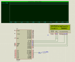
here is the simulation while the counter is measuring the pulse width of a 1Hz signal on INT0. The correct reading should be 500000 (us) as the crystal is a 12Mhz crystal.
 

Attachments

  • C51 Pulse Counter.PNG
    C51 Pulse Counter.PNG
    26 KB · Views: 199
so the accuracy is about 2 / 500000, more than what you need.

---------- Post added at 12:46 AM ---------- Previous post was at 12:42 AM ----------

the shortest pulse this program can measure is about 20K.

if you want to measure a faster pulse, you will have to run the code at higher frequency, or use the prescaler and have to figure out a way to read the prescaler (which takes an extra pin).
 

Thanks millwood for your support.
I will try your code and simulate in Proteus, would you send me hex file of the program so i can load it in the Proteus.
 

I have written the following code to measure the frequency, but there is no accuracy. How I make more efficient code.

My theme for routine is this
>I have to measure the frequency of the signal from 2KHz to 10Hz.
>Frequency is coming at the int0 pin of 18f252 controller.
>In the code i select the value of prescaler so that the timer will not overflow until the ext interrupt (edge triggered) comes.
>when the ext int comes,the value of timer0 will be saved in a variable and then reset the timer.
>display the value on the PC using serial communtication.
Code:
#include <18f252.h> 
#fuses HS,NOWDT,NOLVP,PUT,NOBROWNOUT                  
#use delay(clock=20000000) 
#use rs232(xmit=PIN_C6, rcv=PIN_C7, baud=9600) 

long a; 
                          
#int_TIMER0 
void timer0_interrupt(void) 
{                                        
 set_timer0(0);//if the timer overflows it reset the timer0  
 clear_interrupt(int_TIMER0);          
 enable_interrupts(int_TIMER0);              
 output_toggle(PIN_C1);//if the timer overflows the led toggles.                                  
}                                                          
                          
#int_EXT                    
void EXT_isr(void) 
{                                                              
 a=get_timer0();//when ext interrupt comes,then the value of timer is stored in variable      
 set_timer0(0);//and then reset the timer,                                                                        
 printf(" %lu \r\n",a);//print that value on PC                  
 output_toggle(PIN_C2);//toggle led2                        
} 

void main()                
{                                                              
 setup_timer_0(RTCC_INTERNAL | RTCC_DIV_ 8);//timer is in 16-bit mode,prescaler is 8      
 set_timer0(0);//initially value of timer is 0                    
 enable_interrupts(INT_TIMER0);//enable timer0                  
 ext_int_edge(0,L_TO_H);//when interrupt goes low to high (rising edge) 
 enable_interrupts(INT_EXT);//enable int0                                          
 enable_interrupts(Global); //enable global interrupts 
 while(1)                                  
 {                            
                
 }              
}

Any suggestion for improving the accuracy.
 

your code wouldn't work because you didn't provide a way for it to work.

take a look at the code I provided earlier. with the comments, the thought process is quite clear. I purposed coded it for a generic 8051 so that you have to implement it for your particular platform / compiler but the same thought process applies.

for more accuracy, you should try the gated timer, which is available on most PICs as timer1.
 

Status
Not open for further replies.

Similar threads

Part and Inventory Search

Welcome to EDABoard.com

Sponsor

Back
Top