Continue to Site

Welcome to EDAboard.com

Welcome to our site! EDAboard.com is an international Electronics Discussion Forum focused on EDA software, circuits, schematics, books, theory, papers, asic, pld, 8051, DSP, Network, RF, Analog Design, PCB, Service Manuals... and a whole lot more! To participate you need to register. Registration is free. Click here to register now.

Make a Block Diagram from our schematic

Status
Not open for further replies.

faizun_shev

Junior Member level 1
Joined
Feb 4, 2010
Messages
16
Helped
0
Reputation
0
Reaction score
0
Trophy points
1,281
Location
Ayer Keroh, Melaka
Activity points
1,385
hai guys,

rite now im still doing my final year project but suddenly ihv difficulties in drawing my block diagram.So, i want to seek helps from all members of this forum to fulfill my dream.here i hv attached the file in JPEG
 

It's so tiny I cannot read it. However, in general, simply make a block out of major functional blocks such as power supply, microcontroller, RS232 interface chip etc. The draw wires between them or "bus" connections for multiple connections such as data lines. Bus connections are usually just very wide connections to show there is more than one.

Keith.
 

The resolution of the picture attached is extremely poor. Nothing can be read from the schematic.
 

I don't think it changes my comments earlier, although I wonder why such a small diagram needs a "block diagram". Normally it is used to simplify a complex circuit for discussion and explanation.

Keith.
 

mr keith.. actually, i ady draw my own block diagram. but in this case, i juz want to reconfirm with member's drawing in make sure that my block diagram is correct. ..:|
mr keith, can u draw one for me?? by referring to ur previous post, i still cant see the whole idea. hope u can help me..
 

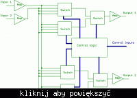
I think you need to learn to draw your own diagram using the guidelines I gave. Here is an example of what a block digram might look like:


The thicker blue lines are to represent "buses" i.e. more than one connection - data lines, address lines etc.

Keith.
 

keith, yours one is juz an example rite ? for ur info, i know a little bit on how to draw the block diagram but as i said b4 this, i juz want to compare my own diagram with member's diagram..huhu

here is my prob: for my diagram, i hv divided the schematic into some blocks that is one block each for pic16f, rs232.power supply and DB9 connector. but im stuck with the UIC00A programmer and the circuit beside it . i dont know wat to represent...

can u give me some tips for better drawing ?
 

Yes, mine is just an example. The UIC programmer is just a connector. You could either leave it off and just have a bus connection to a label saying "UIC connector" or put a box round it as well.

For the reset circuitry - maybe just a box saying "reset circuit" and a couple of connections to the micro.

There aren't any rules to block diagrams as far as I know. They are usually done to help explain things so if something needs explaining it needs to be there somewhere. If it is just a peripheral bit of circuitry you could leave it off altogether.

Keith.
 
ok, tq keith .ill try to correct back my diagram.once finish.ill show you.:D

Added after 1 hours 28 minutes:

bro keith, can u check my diagram. there are 2 circuits. the new picture(7) file is the simple one.meanwhile diagram 1 file is the latest one but still im not satisfying. could u evaluate both the diagram n if necessary please add the part that i missed..:|
 

Status
Not open for further replies.

Part and Inventory Search

Welcome to EDABoard.com

Sponsor

Back
Top