james09
Newbie level 4
For-loop
can anyone help the following assignment?
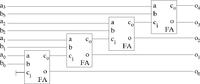
A ripple-carry adder is designed using for-loop construction. The simplest way to describe a ripple-carry adder is to use a chain of 1-bit full-adders (see figure below where 4-bit ripple carry adder is implemented using 1-bit full adders). Each of the full-adders computes the sum of inputs a, b and carry-in ci bits inserted into an output o and carry-out co for the next adder in the chain. Usually the MSB of the sum (o4 in the figure) is not used to keep the input and output widths equal - not all tools can handle different bit-widths directly.
Expand the schematics of the 4-bit adder to calculate 8-bit addition (the 1-bit full-adders are still used). Write a VHDL design with inputs of type std_logic_vector (7 downto 0) and output of type std_logic_vector (8 downto 0). Use prosedure full_adder (download the full adder packet) in a FOR loop to calculate the result. Use temporary variable to store the sum and carry values between rounds. To be able to use the full adder procedure you have to add line use work.full_adder.all in your design. The procedure is called with command full_adder ( a, b, carryin, sum, carryout ) where a and b are the values to be added and sum and carryout are variables to store the results.
Write a testbench and simulate your adder as you did in the part 1 to check correctness of the code. Make sure that all 1-bit adders are used and working, and that the carry is propagated.
Synthesize the design using output external constraint values: 400 ps and 200 ps. Compare with the synthesis results of the signed type based adder.
can anyone help the following assignment?
A ripple-carry adder is designed using for-loop construction. The simplest way to describe a ripple-carry adder is to use a chain of 1-bit full-adders (see figure below where 4-bit ripple carry adder is implemented using 1-bit full adders). Each of the full-adders computes the sum of inputs a, b and carry-in ci bits inserted into an output o and carry-out co for the next adder in the chain. Usually the MSB of the sum (o4 in the figure) is not used to keep the input and output widths equal - not all tools can handle different bit-widths directly.
Expand the schematics of the 4-bit adder to calculate 8-bit addition (the 1-bit full-adders are still used). Write a VHDL design with inputs of type std_logic_vector (7 downto 0) and output of type std_logic_vector (8 downto 0). Use prosedure full_adder (download the full adder packet) in a FOR loop to calculate the result. Use temporary variable to store the sum and carry values between rounds. To be able to use the full adder procedure you have to add line use work.full_adder.all in your design. The procedure is called with command full_adder ( a, b, carryin, sum, carryout ) where a and b are the values to be added and sum and carryout are variables to store the results.
Write a testbench and simulate your adder as you did in the part 1 to check correctness of the code. Make sure that all 1-bit adders are used and working, and that the carry is propagated.
Synthesize the design using output external constraint values: 400 ps and 200 ps. Compare with the synthesis results of the signed type based adder.
