Welcome to our site! EDAboard.com is an international Electronics Discussion Forum focused on EDA software, circuits, schematics, books, theory, papers, asic, pld, 8051, DSP, Network, RF, Analog Design, PCB, Service Manuals... and a whole lot more! To participate you need to register. Registration is free. Click here to register now.
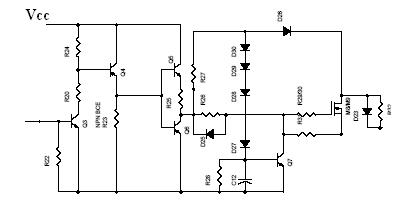
Output is connected to primary of the transformer.The circuit shown is only one leg actually full circuit is a PUSH PULL inverter which consists of same circut connected to other end of transformer.
The last resistor is snubber its is in complete leave it.
I want to know is when the 5th(left to right)transistor is turned on.If that transistor is turned on there will be no pulse to MOSFET so mosfet is turned off.
This is circuit is for overload detector if output is overloaded the MOSFET has to switch off. How to switch off the mosfet the only way is,to turn on the transistor(5th one).How????
This site uses cookies to help personalise content, tailor your experience and to keep you logged in if you register.
By continuing to use this site, you are consenting to our use of cookies.