Areal Person
Newbie level 4
digital modulation circuits
Ok, Here’s a circuit I’ve been working on, It’s a good experimentation circuit for a beginner. Could some of the experts please check my findings and advise me of my mistakes. This is only the third circuit I’ve ever done. I’m teaching myself as I go. However, I’m hoping that I’m right. I’m sorry I can give any detail values, my scope is old and I don’t know what I’m doing. I’m trying to learn.
Thanks for any help anyone can offer.
****************
Observations
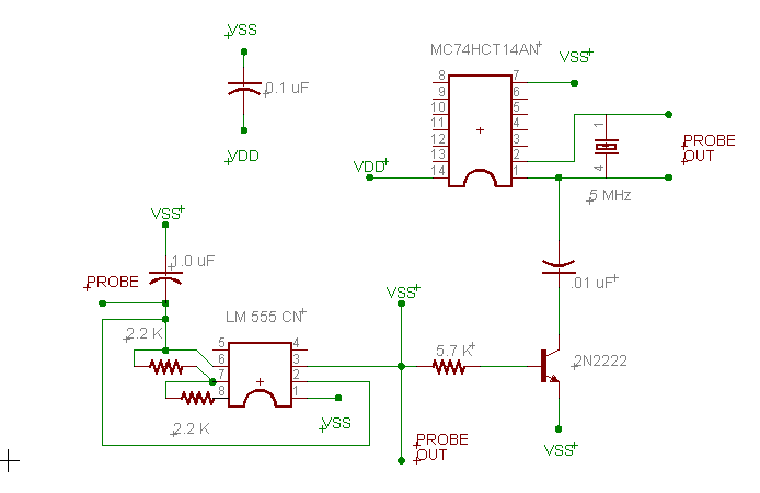
I’ve managed to build this 555 circuit VDD is 5vdc; it uses a Schmitt trigger inverter to drive a crystal which is used for a carrier wave, the output square wave goes into a TTL circuit which modulates the square wave onto the crystals sine wave.
The two 2.2 K resistors on the 555 along with the 1.0 uF cap determine the duty cycle for the 555’s astable mode square wave. If you use a wire or a switch at the VSS Probe OUT junction just before the 5.7 K resistor you can see the signal being modulated on a scope as you probe the crystals BOTTOM output line.
Some Notes:
The frequency of the 555’s square is different from the crystal, this makes it easy to see the modulation on the carrier. It seems that the 555 circuit changes the amplitude of the carrier out put signal to a fixed value but not it’s frequency.
The circuit needs to be tuned much better for final use.
It seems a good next step would be to change the 555 square wave to be a input bit stream from a PC, and add a class-C amp for RF applications
**************
What do you think, Where am I wrong ?
Thanks,
-Areal
Here's the circuit...
