Continue to Site

Welcome to EDAboard.com

Welcome to our site! EDAboard.com is an international Electronics Discussion Forum focused on EDA software, circuits, schematics, books, theory, papers, asic, pld, 8051, DSP, Network, RF, Analog Design, PCB, Service Manuals... and a whole lot more! To participate you need to register. Registration is free. Click here to register now.

The formula for TMR0 calculation

Status
Not open for further replies.

expert

Member level 2
Joined
Nov 28, 2007
Messages
50
Helped
0
Reputation
0
Reaction score
0
Trophy points
1,286
Activity points
1,626
BEGIN CLRF PORTB
WAITHI BTFSS PORTA,0
GOTO WAITHI
CLRF TMR0 ;START TMR0
TESTST BTFSC PORTA,0
GOTO TESTST
MOVF TMR0,W ;READ TMR0 INTO W
SUBLW .148
BTFSC STATUS,CARRY
GOTO WAITHI

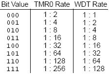
i'm using a 4Mhz cystal and the prescaler is 1:1
do anyone know how to calculate the value for .148
the answer should approximate to 7ms ?
can anyone provide me the formula and calculation??
thxs
 

tmr0 carry

Hi!
I supose u r using a PIC. For TMR0, 1:1 prescaler doesn't exist.

Added after 37 minutes:

The formula is this:

N * fXTAL/4=(256-T) * pres;

N -> cycles
fXTAL -> crystal frequency
T -> value of the timer
pres -> the prescaler value

In your case using a 4MHz XTAL, 1:256 prescaler (pres=256) and 7ms:

7000us*4MHz/4=(256-T)*256

T=256-7000/256=228,65625 -> T=229

With this value you'll obtain 6912us = 6.912 ms
 

calculate prescaler tmr0

Code:
BEGIN    CLRF PORTB                                 ; measure start bit
WAITHI   BTFSS PORTA,0
         GOTO WAITHI
         CLRF TMR0 ;START TMR0
TESTST   BTFSC PORTA,0
         GOTO TESTST
         MOVF TMR0,W ;READ TMR0 INTO W
         SUBLW .148
         BTFSC STATUS,CARRY
         GOTO WAITHI 

TESTA0H	BTFSS	PORTA,0                         ; measure logic 1 or 0
	       GOTO	TESTA0H
	       CLRF	TMR0
TESTA0L	BTFSC	PORTA,0
	       GOTO	TESTA0L
	       NOP
	       MOVF	TMR0,W
	       SUBLW	.90
	       BTFSS	STATUS,CARRY
	       BSF		temp
actually i'm doing an infrared program, the coding above is the receiver part whic has to decode the data which transmited from the transmitter side
they is a start bit = 7.5ms , logic 1 = 5ms and logic 0 = 2.5ms
the coding above will measure the pulse width and subtract the SUBLW .148 value
while for differentiate 1 and 0 , i put a SUBLW .90, the value is between 5ms and 2.5ms , so that i can find out whether is logic 1 or zero to store
i'm using a pulse width signal for the infrared transmisssion
mayb u will feel weird that y i don know how to calculate and can get the value of 148 and 90, this is because i directly testing use hardware by different value
so that i suppose to get the answer after testing for 30times ++ , but i duno how how to use the 148 and 90 to calculate ??
148 value should between 7.5ms and 5ms, while 90 should between 5ms and 2.5ms.
thxs for helping!!
 

tmr0 calculation

aupa said:
Hi!
I supose u r using a PIC. For TMR0, 1:1 prescaler doesn't exist.

TMR0 prescaler = 1/1 DO EXIST, when you assign prescaler to watchdog. Refer to any PIC datasheet.
 

18 pic prescaler calculation

soli ,i move b'00000010' to option_R so my setting for prescale should be 1:8
 

Re: TMR0 calculation

i still cound find out the answer!!!!
thxs for helping!!!
 

Re: TMR0 calculation

expert said:
i still cound find out the answer!!!!
thxs for helping!!!

OK first, are you sure your logic is correct? Your initial logic seems to be waiting for a high, then timing a high pulse. Most modules output low, so a start bit is a low pulse not high.. Of course you could have an inverter or different module, but it's the first thing to check. Light carrier = Low on almost all modules, so if you have a module hooked straight to a pin this is likely it. Also check, some modules need an external pullup resistor too, but most have at least a weak one inside..


Secondly instead of a double lock like that I've generally found it's more successful to simply have a running count and only look for end transitions. Once you get an end of bit, do multiple subtracts for length to see if it was a 1, 0, or start, or overrange (ignore as bit and reset the decode) width, then add to the current decode and clear your running count for the next bit. This could be a bit more difficult as a running count in straight code, but as an interrupt routine it makes it easy. The time between interrupts makes for a divide, so if you do it right and just add one to your own counter on each interrupt, your valid pulse measurements will easily stay within one byte.

Timing variations on real remotes are crazy too, you want to get at least 2 or 3 of the same valid code before deciding it's real, 1 of even with checksum etc could easily get a false code now and then.
 

Re: TMR0 calculation

Excuse me nguyennam!

The prescaler im refering to is of the timer0, not using the watchdog.

50_1206893345.jpg
 

Status
Not open for further replies.

Part and Inventory Search

Welcome to EDABoard.com

Sponsor

Back
Top