Continue to Site

Welcome to EDAboard.com

Welcome to our site! EDAboard.com is an international Electronics Discussion Forum focused on EDA software, circuits, schematics, books, theory, papers, asic, pld, 8051, DSP, Network, RF, Analog Design, PCB, Service Manuals... and a whole lot more! To participate you need to register. Registration is free. Click here to register now.

ultrasonic driver circuit

Status
Not open for further replies.

mayur.kulkarni

Newbie level 1
Joined
Jan 2, 2008
Messages
1
Helped
0
Reputation
0
Reaction score
0
Trophy points
1,281
Activity points
1,291
we r implementing an ultrasonic ranger as a project. we hv designed pulse generator. but v r unable to get amplification using following circuit.please help


69_1199297735.jpg


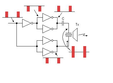
it uses inverters. but v r not at all getting amplification.instead v r getting attenuated output square wave. plz help

Added after 5 minutes:

we implemented this circuit using 74LS04 as well as HEF4049 hex inverters. but output is same. we want to amplify 11.5 V peak to peak square wave from astable multivibrator IC555
 

ultrasonic driver

With the given information, it is difficult to be sure. It looks like the transducer is a piezoelectic device and therefore capacitive. Perhaps this is the problem. Increase the value of C, or remove it all together ( there is no DC path through a piezo transducer)

Humber
 

ultrasonic ranger driver

you can not amplify the signal. Only You can drive the piezo bidirectionally.
 
piezo driver circuit ultrasone

You are correct Hunter, but I think mean to get an output that is twice that of a single driver by using differential drive.

Humber
 
ultrasonic driver differential

Hi Humber,
Supply CMOS IC with max VCC. This will be enough, I think.
Regards.
 

Status
Not open for further replies.

Similar threads

Part and Inventory Search

Welcome to EDABoard.com

Sponsor

Back
Top