Continue to Site

Welcome to EDAboard.com

Welcome to our site! EDAboard.com is an international Electronics Discussion Forum focused on EDA software, circuits, schematics, books, theory, papers, asic, pld, 8051, DSP, Network, RF, Analog Design, PCB, Service Manuals... and a whole lot more! To participate you need to register. Registration is free. Click here to register now.

Relay problem with my computer

Status
Not open for further replies.

realin

Newbie level 6
Joined
Jun 17, 2007
Messages
13
Helped
0
Reputation
0
Reaction score
0
Trophy points
1,281
Activity points
1,386
Hi guys,

I made an easy circuit to turn on/off my router from computer using parallel port interrupt. Now the problem is, whenever my computer turns on, the relay itself gets ticked and the router goes on. And if i connect to the other side of relay, the router gets on when i shut down the computer, i mean when the computer is just shut down from windows, and when it turns off its motherboard and everything, the relay ticks

Is there a solution to this problem ?

Also i need an advice from you guys, that if it is possible to send interrupt using USB ? like we have to send +5v to the circuit and it gets on and if we send 0 then it gets off, the same voltage can be given thru USB also ? if yes, then do you know how to do it ? which language ?

thanks for ur time

I have attached the circuit image along with this post :)
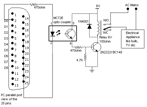
86_1186032779.gif

[/img]
 

and where i am suppose to fit that flip flop? sorry for my bad coz i am a computer student.. i believe flip flop is used to send data in bits no ?

thanks for ur time
 

it is due to the spike that the computer sends when it is turned on or off... you better use a capacitor in series with the led of the opto coupler to smoothen the spike to avoid false triggering...
 

is capacitor having 1000 µF would work ?? and I am suppose to put in series after opto coupler or befire it ??

thanks
 

putting it before is a better idea.... but remember increasing the capacitor time will increase to the switch on time of your led so better use a medium value capacitor... you can experiment with the capacitor values to find the suitable one.... i feel 1000µ is too high..
 

Hi,

It is not spike, when you start your computer, data are sent to the parallel port for the detection of new hardware by windows. It is the reason why you turn on / and off your relay.

Try with the line autofeed (14) or init (16) or select in (17) of the parallel port.
 

first i too thought it to be that only... but i think the system disables all its ports when we shut down and there is no reason for the relay to be triggered when the system shutsdown....

correct me if i am wrong...
 

The message of Realin is not very clear.
He talks about the other side of the relay. What does he mean by other side of the relay ? NC connection ?

If yes, when turn of your computer, you turn on the relay.
 

Well i would elaborate the whole thing..

First i made the circuit as shown above.. Now relay has three points, one is common and other two are for switching..

When I send value 1 from computer, the relay ticks and the circuit is on..

When i send value 0, the relay ticks again and the citcuit is off.

Well everything was working quiet well as planned, but until i pass the value 0 and switched off the computer, to my surprise the circuit got on when the computer shut down itself.

So it means, when the computer is shut down, it sends signal to parallel port,like an interrupt to shut down the device..

So to avoid that i.e. to avoid my device to turn on again after the computer shutdown, i have to change the relay points of the circuit, so that even if it ticks, it ticks the circuit to go off and not on..

SO MY CONCERN IS :-

To avoid the interrupt when the computer turn on/off

thanks for ur time and concern :)
 

actually the transistor should also turn off because the transistors base drive is lost once the led goes off.... if the system is shut down then the power to the led is also gone (in a few seconds if the system sends a signal before it shuts down)... i think there must be some problem with the optocoupler... better test whether it is working properly...
 

test an optocoupler how ? I am sorry as i told u .. i am a computer student.. but i can do things, if u just guide me.. thanks :)
 

k... you simulate things by connecting pin2 of the optocoupler to the ground and giving 5V(as if the computer gives) to pin1 and watch if the relay switches.... now remove that 5V and see if the relay switches... if it does then things are fine... if it doesn't switch back then there is something wrong with the optocoupler...
 

A.Anand Srinivasan said:
k... you simulate things by connecting pin2 of the optocoupler to the ground and giving 5V(as if the computer gives) to pin1 and watch if the relay switches.... now remove that 5V and see if the relay switches... if it does then things are fine... if it doesn't switch back then there is something wrong with the optocoupler...

oh i gues everything is fine but now i messed everything..

there are two chances
1. my computers parallel port is damaged
2. The opto-coupler is RIP

So how this happened?

Well as written above, i tried to give +5v from USB wires to the optocoupler's 1 PIN. But i dont know what was wrong it just ticked relay once and then it never say a word to me :(

I guess i damaged something within my circuit or my parallel port.

I donn know if i was to unplug some wires, i just sent the LOW signal from computer and then applied +5v but everything blew up.

Now i gotta go downtown and get another optocoupler and some stuff like this to test what is damaged, if before that you can tell me waht happened ?


thanks a lot :)
 

giving 5V from some adapter or some power supply was the basic idea because they can supply enough current... i'm not sure how much current the USB can source... did u try plugging in a thumbdrive in the USB slot to check whether it is working???... do that and then decide which has been damaged....
 

hi,

ya the USB port is working quite fine.. i guess it is the parallel port or the optocoupler which blew up.. i will check it later today by replacing optocoupler
 

now i think i got a glimpse of what the problem might be.... you must have applied 5V directly to the optocoupler LED... sorry... actually you have to have a resistor to minimize the current... i forgot to mention that.... the 470Ω in series with the LED is for that purpose only,,,,...
 

got a new optocoupler, gonna fix it and let you know guys :)

Added after 2 hours 8 minutes:

oh my god my new motherboard's parallel port is dead :( .. guys is there a way to fix it ?

cause i tried putting a new optocoupler and it gave no response, but when i tried to shot circuit the circuit like just touching contacts, the relay just triggered.. that means the whole circuit works quite fine when i touch the pins 4-5 of old as well as new optocoupler without or even with the computer signal :(

that means my parallel port is fucked up :(

Now i am left with other chance to pass interrupt with USB, tell me guys is it possible ??
 

please dont risk things with your computer output.... try using a separate supply.... or try it with three 1.5V batteries in series...

the output of computer ports are designed with certain current and voltage limitations....
 

    realin

    Points: 2
    Helpful Answer Positive Rating
Before you go any further with experiments on "live" parallel port, build yourself a tester .. see picture below (more details at: **broken link removed** )
Then, cool down, make yourself a cup of tea (or coffee) ..
Connect tester to the parallel port and check it out .. maybe some of D-pins are still OK ..

Regards,
IanP
 

    realin

    Points: 2
    Helpful Answer Positive Rating
Status
Not open for further replies.

Part and Inventory Search

Welcome to EDABoard.com

Sponsor

Back
Top