Mithun_K_Das
Advanced Member level 3
- Joined
- Apr 24, 2010
- Messages
- 899
- Helped
- 24
- Reputation
- 48
- Reaction score
- 26
- Trophy points
- 1,318
- Location
- Dhaka, Bangladesh, Bangladesh
- Activity points
- 8,252
I uploaded proteus DNS file, proteus 7.8 sp2.
Anyway: update:
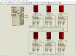
Tell me if I'm in right way... I've just tested with 2 3X1 digits. And will extend step by step.
- - - Updated - - -
update:

So I'm in right way, right?
- - - Updated - - -
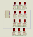
Now its 10 display so far.... & I'll try up to the end...

Hope you like it.
Anyway: update:

Code:
/*******************************************************************************
* Program for, Shift Register Display test for multiple digits                 *
* Program Written by_ Engr. Mithun_K_Das, mithun060@gmail.com                  *
* MCU:PIC16F877A; X-Tal: 20MHz                                                 *
* Date: 07-09-2017                                                             *
*******************************************************************************/


Digit_conversion(char digit)
{
   switch(digit)
   {
      case 0: digit = 0x3F; return digit;
      case 1: digit = 0x06; return digit;
      case 2: digit = 0x5B; return digit;
      case 3: digit = 0x4F; return digit;
      case 4: digit = 0x66; return digit;
      case 5: digit = 0x6D; return digit;
      case 6: digit = 0x7D; return digit;
      case 7: digit = 0x07; return digit;
      case 8: digit = 0x7F; return digit;
      case 9: digit = 0x6F; return digit;
   }
}

unsigned int number1=0, number2=0;
int digit=0;
void Disp_number1(unsigned int value)
{
   digit = (value/1u)%10;
   Spi_Write(Digit_conversion(digit));
   digit = (value/10u)%10;
   Spi_Write(Digit_conversion(digit));
   digit = (value/100u)%10;
   Spi_Write(Digit_conversion(digit));
}
void Disp_number2(unsigned int value)
{
   digit = (value/1u)%10;
   Spi_Write(Digit_conversion(digit));
   digit = (value/10u)%10;
   Spi_Write(Digit_conversion(digit));
   digit = (value/100u)%10;
   Spi_Write(Digit_conversion(digit));
}
void Update_display()
{
  PORTC.F6=1; //one latch clock
  PORTC.F6=0;
}
void main()
{
  TRISC = 0x00;
  PORTC = 0x00;
  CMCON = 0x07;
  ADCON1 = 0x07;
  SPI1_Init_Advanced(_SPI_MASTER_OSC_DIV4, _SPI_DATA_SAMPLE_MIDDLE, _SPI_CLK_IDLE_LOW, _SPI_LOW_2_HIGH);
  while(1)
  {

      number1 = 123;
      number2 = 789;
      Disp_number1(number1);
      Disp_number2(number2);
      Update_display();

  }

}
Tell me if I'm in right way... I've just tested with 2 3X1 digits. And will extend step by step.
- - - Updated - - -
update:

HTML:
/*******************************************************************************
* Program for, Shift Register Display test for multiple digits                 *
* Program Written by_ Engr. Mithun_K_Das, mithun060@gmail.com                  *
* MCU:PIC16F877A; X-Tal: 20MHz                                                 *
* Date: 07-09-2017                                                             *
*******************************************************************************/


Digit_conversion(char digit)
{
   switch(digit)
   {
      case 0: digit = 0x3F; return digit;
      case 1: digit = 0x06; return digit;
      case 2: digit = 0x5B; return digit;
      case 3: digit = 0x4F; return digit;
      case 4: digit = 0x66; return digit;
      case 5: digit = 0x6D; return digit;
      case 6: digit = 0x7D; return digit;
      case 7: digit = 0x07; return digit;
      case 8: digit = 0x7F; return digit;
      case 9: digit = 0x6F; return digit;
   }
}

unsigned int number1=0, number2=0,number3=0,number4=0;
int digit=0;
void Disp_number(unsigned int value)
{
   digit = (value/1u)%10;
   Spi_Write(Digit_conversion(digit));
   digit = (value/10u)%10;
   Spi_Write(Digit_conversion(digit));
   digit = (value/100u)%10;
   Spi_Write(Digit_conversion(digit));
}
void Update_display()
{
  PORTC.F6=1; //one latch clock
  PORTC.F6=0;
}
void main()
{
  TRISC = 0x00;
  PORTC = 0x00;
  CMCON = 0x07;
  ADCON1 = 0x07;
  SPI1_Init_Advanced(_SPI_MASTER_OSC_DIV4, _SPI_DATA_SAMPLE_MIDDLE, _SPI_CLK_IDLE_LOW, _SPI_LOW_2_HIGH);
  while(1)
  {

      number1 = 123;
      number2 = 789;
      number3 = 256;
      number4 = 512;
      Disp_number(number1);
      Disp_number(number2);
      Disp_number(number3);
      Disp_number(number4);

      Update_display();

  }

}
So I'm in right way, right?
- - - Updated - - -
Now its 10 display so far.... & I'll try up to the end...

Hope you like it.