Continue to Site

Welcome to EDAboard.com

Welcome to our site! EDAboard.com is an international Electronics Discussion Forum focused on EDA software, circuits, schematics, books, theory, papers, asic, pld, 8051, DSP, Network, RF, Analog Design, PCB, Service Manuals... and a whole lot more! To participate you need to register. Registration is free. Click here to register now.

The neutral potential and a battery ground

Status
Not open for further replies.

julian403

Full Member level 5
Joined
Feb 28, 2014
Messages
254
Helped
1
Reputation
2
Reaction score
1
Trophy points
18
Location
Argentina
Activity points
2,105
Hello. I want to measure the distribution voltage signal, the 110V @60 Hz or the 220V @50Hz. To do that I will use an ADC. If I don't use opto acopler to make an isolation. Can I connect the battery ground and the signal neutral to have the same reference? It's possible that between a batery ground and the neutral of the 110V be a potential difference? I think no, but I'm not sure and to avoid any problem in the test I want to make this question here.

Regards.
 

It's always dangerous to work directly on the mains voltages.
Any accidental touching of the mains can be fatal.

What do you plan on doing with the digital voltage reading from the ADC?
 
Hi,

Technically possible.
But from safety viewyou should avoid this.
Don't risk your or anybody else's health.

Klaus
 
Safety rules don't allow assumptions about neutral potential against ground. Neutral is treated as hazardous contact voltage as well.

Respectively you need true isolation or sufficient high impedance differential voltage dividers for a safe mains voltage measurement.
 
Well the voltage divider is 1000000:1000 so the digital circuit would get a phase voltage of 0.2 V if the rms voltage is 220 V or 0.1 V if the rms voltage is 110V. But you made me think about the safety. What I didn't want is use opto acopler because it hasn't a long life period and as every semicondutor it has a little distortion and the transformer as it follow the faraday law, it's has a non plane frecuency response.
 

Hi,

What I didn't want is use opto acopler because it hasn't a long life period and as every semicondutor it has a little distortion and the transformer as it follow the faraday law, it's has a non plane frecuency response.
* What lifetime do you expect? Many, many, many industrial equipment use optocouplers and have a 24/7 lifetime of 20..50 years
* what 50Hz / 60Hz deviation do you expect? With a suitable, non saturating core it should be easily possible to be below 0.1% deviation.

To me it seems both your doubts are not reasoned.

Klaus
 
Thank you. By the way. Do you know what presicion are the Opto acopler. For example the PC817 in the datasheet don't say the presicion. It's smaller than 1%? That would be great.
 

The PC817 and all other optocouplers have an LED side and a sensor side. Each has it's own properties and operating conditions so 'precision' doesn't really matter. They do have a minimum current transfer ratio which is a measure of input current against output current but it is for indication only, it shouldn't be trusted to give a particular output for a particular LED current.

I'm not sure how you are going to use a 1000:1 voltage divider to drive an LED anyway as they are current operated not voltage. You would have to set a maximum current for the LED based on peak AC voltage, for example if you wanted 20mA (typical for a PC817) at a peak of 220V RMS AC, you would use a single resistor of (311 - 1.4)/0.02 = ~15.5K.

True, optocouplers do degrade over time so schedule a replacement in about the year 2070 !

I strongly advise that you do not connect directly to neutral, electrically it will work but the risk is very high and all your circuit could easily become 'live' and very dangerous.

Brian.
 
In this case, when the 220V AC is inverse, what I means it's when the phase is negative respect the neutral if I do a diode- resistance circuit, all the voltage would drop in the diode which it's inverse polarizate. So a √2 * 220 V is going to drop in the diode in some moments.

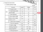
Looking the PC817's datasheet I found:

Capture.PNG

What's that inverse voltage?
 

Hello julian403,
Inverse voltage concerning diodes is the maximum amount of voltage that opposes the reverse bias of the diode.
eg. Due to mains AC voltage periodically reversing in polarity, a diode will allow forward conduction in one direction only,
depending on how its configured. If the anode of the diode is in contact with the AC voltage, it will produce positive going
pulses and block any negative transitions out of its cathode. Its this blocking that is the maximum inverse voltage that
the device can tolerate.
Sorry about the long winded explanation.
Regards,
Relayer
 

To further expand on that...

The maximum reverse voltage (6V in the image) is the highest voltage the manufacturer has designed the device to withstand when the polarity is against conduction. Being a diode, when the voltage is in the conducting direction, current will flow and voltage therefore dropped in the series resistor, in fact the voltage across the LED will go no higher then Vf (typically between 1.4 and 1.8V for an optocoupler).

So on the conducting half cycle of the AC, the voltage across the LED rises to about 1.4V then the current through it starts to increase and the voltage stays fairly stable. On the reverse polarity half cycle, the voltage will rise to around 6V with no current flowing then it gets destroyed!

You can fix the problem in one of three ways:
1. add another diode with high voltage rating in series with the LED. This prevents the reverse voltage reaching the LED.
2. add a low voltage diode across the LED wired so it conducts in the other direction. This limits the reverse voltage to Vf of the new diode.
3. add four diodes in a bridge configuration, this steers both half cycles so they arrive in the conducting polarity at the LED.

Brian.
 
The PC817 discussion sounds confusing to me. Are you talking about a digital (e.g. voltage presence or zero crossing? detector or an analog voltage measurement. An standard opto coupler isn't suited to isolate analog signal without modulation (e.g. sigma-delta, V/f, serial transmission of ADC data).
 
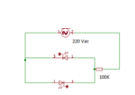
What do you think about this circuit?

Capture.PNG

Are you talking about a digital (e.g. voltage presence or zero crossing? detector or an analog voltage measurement. An standard opto coupler isn't suited to isolate analog signal without modulation (e.g. sigma-delta, V/f, serial transmission of ADC data).
I want to sense with the ADC the signal to make the FFT to measure the power factor, taking in care the THD. The current would sense with a hall efect sensor.
 

Hi,

This is the most problematic circuit regarding:
* precision
* distortion
* long time stability.
Additionally a PC817 is not suitable at all for this analog solution.
Performing an FFT on the output signal gives no meaningful information.

As suggested by FvM.... a digital modulator gives way better results.
Consider to use three optocouplers to isolate a SPI interface and use an ADC on the high voltage side.

Klaus
 

As for possible analog isolation solutions, you should review Vishay IL300 optocoupler. Check if the linearity and gain stability fulfills your requirements.

Texas Instrument AMC1200 is an example of a recent isolation amplifier SD modulation to convert the signal to digital.

You don't necessarily need harmonic analysis to determine the distortion power factor, it's sufficient to process, real, reactive and apparent power. A recent energy meter chip can achieve this.
 
FvM that's is what I was looking for.

- - - Updated - - -

FvM that's is what I was looking for. :thumbsup:
 

Status
Not open for further replies.

Part and Inventory Search

Welcome to EDABoard.com

Sponsor

Back
Top