Continue to Site

Welcome to EDAboard.com

Welcome to our site! EDAboard.com is an international Electronics Discussion Forum focused on EDA software, circuits, schematics, books, theory, papers, asic, pld, 8051, DSP, Network, RF, Analog Design, PCB, Service Manuals... and a whole lot more! To participate you need to register. Registration is free. Click here to register now.

EBG cell simulation.

Status
Not open for further replies.
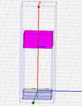
Your PML need to be placed on the outer edge of your bounding (vacuum) box. It can't be inside or intersect with another (your Box3 object).

Thank you Mr.planarmetamaterials. But in the tutorial, they were given instructions to create two air boxes( confused .... Any explanation for that?).
 

OK, so it looks like the tutorial uses another air box for the express purpose of supporting boundary conditions -- thats fine. As per the tutorial, "Therefore, another airbox has to be created with encloses the original airbox and PML". Make sure that this box does not intersect with the PML; it should completely enclose it.
 
Hi, Planarmetamaterials. i have modified the design as you suggested but the warning still coming. what should I do?

airbox.pngwarning.png
 

Hello, planar metamaterial, i did that also still that warning showing up.... Can i ignore it?
 

It is always better not to get any warnings but you can go ahead and check filed and other parameters and compare them with some reference. You can also resolve this issue by assigning priority to the boundary in the overlapping region
 
You could ignore the warning if that's the case, but you can also do an alternate technique (which is what I do):

Instead of the outer box, simply place sheets along the original vacuum box, and make sure they extend over the entire face of the domain (including the PML). Apply the M/S boundaries to these sheets. No need for sheets on the top and bottom.

In either case, good luck!
 
Hi, planarmetamaterials.... the alternative technique you suggested was working.....Final doubt....To plot the Dispersion diagram i need to find the frequency isn't it? ....i am thinking like this.....Beta=2*Pi/Lambda.....Lambda=C/f..... what value should i put in the Beta variable?

- - - Updated - - -

Meanwhile i have designed a EBG based slot antenna paper from IEEE.... i have designed the Unit cell and i got the frequency phase shift diagrams similar to the ones on the paper....but i desinged the whole antenna Hfss stops the simulation process abruptly....can you please suggest me what should i do.View attachment array1.rar
 

Master/Slave boundaries take a phase shift, where the phase along an axis is given by Beta*d, with d being the period of the unit cell. The first Brillouin zone is bounded by Angle = [0,180] degrees.
 

Status
Not open for further replies.

Part and Inventory Search

Welcome to EDABoard.com

Sponsor

Back
Top