Continue to Site

Welcome to EDAboard.com

Welcome to our site! EDAboard.com is an international Electronics Discussion Forum focused on EDA software, circuits, schematics, books, theory, papers, asic, pld, 8051, DSP, Network, RF, Analog Design, PCB, Service Manuals... and a whole lot more! To participate you need to register. Registration is free. Click here to register now.

type of feedback in the 2nd stage of a 2 stage OTA

Status
Not open for further replies.

tenso

Advanced Member level 4
Joined
Feb 18, 2015
Messages
110
Helped
3
Reputation
6
Reaction score
2
Trophy points
1,298
Activity points
2,399
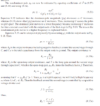
I wanted some clarification as to the type of internal feedback present in the second common source gain stage in a 2 stage OTA where the gate and drain are connected with a miller capacitor. I thought it was shunt-shunt type of feedback but Gray-Meyer seems to say that it is series-shunt. I was reading the section where they try to derive the non-dominant pole by just observing the pole at the output and not solving the small-signal model's transfer function. I am attaching the page in chapter 9 of the fifth edition where they do this.
Capture.PNG

Here C is the miller capacitor. C1 is the shunt cap at output of first stage and C2 is the shunt cap at output of 2nd stage. Since the output resistance Ro is reduced by 1+T, we have shunt sensing at the output. The calculation of the feedback factor f tells me that that is series-shunt feedback.

but it seems to me that a current signal is being fed back into the input and that it is shunt-shunt? it seems that I am wrong but I was hoping someone could help me to see how it is series-shunt for the second common source stage.
 

Can not tell you if this is shunt-shunt or not. Just want to point out one important message in that page of textbook.

Before putting any miller cap C, the output pole is at 1/(R2*C2). After adding a miller cap C across the drain and source of that mos, it looks like a 1/gm mos diode. So, the output is at 1/(1/gm*(C1+C2)) Since 1/gm<<R2, the output pole is moved to very high frequency.

I am familiar with the concept of pole splitting. But I was wondering how they go about solving the equations 9.33
With how the calculate the feedback factor f, it seems the 2nd stage is series-shunt. I want to know why that is the case
 

didn't know thread bumping is against the rules.
so clarifying the question if the opening post is not clear.

What kind of feedback is present in the second common source stage ( with the miller cap) in a 2 stage OTA? Gray and Meyer seem to state it is series-shunt and use that to get the expression for the second pole. To me it seems like that we have shunt-shunt feedback because a current signal is being fed back
 

Status
Not open for further replies.

Similar threads

Part and Inventory Search

Welcome to EDABoard.com

Sponsor

Back
Top