Continue to Site

Welcome to EDAboard.com

Welcome to our site! EDAboard.com is an international Electronics Discussion Forum focused on EDA software, circuits, schematics, books, theory, papers, asic, pld, 8051, DSP, Network, RF, Analog Design, PCB, Service Manuals... and a whole lot more! To participate you need to register. Registration is free. Click here to register now.

help in customizable PTM models

Status
Not open for further replies.

oAwad

Full Member level 2
Joined
Feb 15, 2017
Messages
136
Helped
0
Reputation
0
Reaction score
0
Trophy points
16
Activity points
1,312
Hello all,

I'm trying to use the Nano-CMOS customizable model generator (URL:http://ptm.asu.edu/) to generate 45nm NMOS and PMOS transistor models with 0.1V threshold voltage. However, when I specify Vth=0.1V (and keep all other variables as default), I get this graph (see attached picture) which shows Vth way far from 0.1V and when I open nominal model I find Vth0=0.411
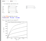
image.png

If someone used this generator before, I have some simple questions:
1) In attached picture, Vth has two input bars...does the second bar defines the undefined region between high and low...or they're just two ways of inputs (one for volts and one for milli-volts) ?
2) Can I decrease threshold voltage to any value or there is a minimum value ?
3) Can anyone tell me/give me some references to know how these variables affect threshold voltage, setup and hold time of transistors ?
 

Hello all,

I'm trying to use the Nano-CMOS customizable model generator (URL:http://ptm.asu.edu/) to generate 45nm NMOS and PMOS transistor models with 0.1V threshold voltage. However, when I specify Vth=0.1V (and keep all other variables as default), I get this graph (see attached picture) which shows Vth way far from 0.1V and when I open nominal model I find Vth0=0.411

View attachment 137961

If someone used this generator before, I have some simple questions:
1) In attached picture, Vth has two input bars...does the second bar defines the undefined region between high and low...or they're just two ways of inputs (one for volts and one for milli-volts) ?
2) Can I decrease threshold voltage to any value or there is a minimum value ?
3) Can anyone tell me/give me some references to know how these variables affect threshold voltage, setup and hold time of transistors ?

1) I don't see any bars.
2) 0.1V and 17nm effective L for a 45nm tech doesn't sound wise. I doubt the model can work accurately for this scenario. How are you picking these values?
3) transistors don't have setup/hold time. you need a cell for that.
 

1) I don't see any bars.
2) 0.1V and 17nm effective L for a 45nm tech doesn't sound wise. I doubt the model can work accurately for this scenario. How are you picking these values?
3) transistors don't have setup/hold time. you need a cell for that.

Sorry if I was not clear. By input bars I mean the two input boxes in front of Vth. They didn't provide any instructions for this online tool so I'm not really sure about there usage. My intention is to create a 45nm NMOS & PMOS model with Vth=0.1V for some simulations and there's no fabrication constraints, so if I decreased Leff will it help ?
and can you suggest values for such a model ? (Vdd = 1.1V)

- - - Updated - - -

and regarding setup/hold time of a logic cell (ex. DFF)...is the definition of setup/hold time is that input should be constant during this time or generally greater than cell threshold voltage ? (so maybe varying but still above cell threshold) in case of logic 1
 

Status
Not open for further replies.

Part and Inventory Search

Welcome to EDABoard.com

Sponsor

Back
Top