rizni
Newbie level 2
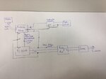
I have got a tattoo removal laser that I am triggering using PC104. The PC104 sends a signal to a relay board which triggers the laser. There is a photodiode that is connected to Arduino and this photodiode detects laser light when the laser fires. The signal from PC104 that activates the laser also goes to the arduino digital input.
The process:
Since it is a tattoo removal laser, the time when you send the signal from PC104 to the laser to activate and when the laser actually fires (emits light) varies. I need to measure the exact time difference between when we send the pulse to the laser from PC104 and exactly when the laser fires. For this, I have connected the signal coming from PC104 to the relay board as well as to one of the digital inputs of Arduino. So, I start measuring the time when the Arduino receives this pulse and then the Arduino waits for the photodiode to detect light coming out of the laser. This tells me the time difference I am looking for.
The problem:
When the laser is powered off, and I send the pulse from PC104 to the relay board and the Arduino, the relay turns ON, since the laser is not powered ON, it does not trigger and the photodiode keeps on waiting for the laser light. As I bring an LED closer to the photodiode manually, it triggers and the process finishes.
The problem happens when the laser is Powered ON and the photodiode is intentionally covered with a black material so it does not see any light. It is kept physically away from the laser light too. THe PC104 sends a signal to the relay board, the relay gets activated, the laser fires, but the system does not wait for the photodiode to detect the light and it finished the cycle. Through Arduino's serial monitor I can see a HIGH on photodiode input when the laser shines. I suspect there is noise coming from the relay board which is causing the Arduino to trigger falsly.
Notes
I have connected a capacitor on the supply pins of the relay coil but it does not change anything.
Any help in this regard will be highly appreciated.
