Continue to Site

Welcome to EDAboard.com

Welcome to our site! EDAboard.com is an international Electronics Discussion Forum focused on EDA software, circuits, schematics, books, theory, papers, asic, pld, 8051, DSP, Network, RF, Analog Design, PCB, Service Manuals... and a whole lot more! To participate you need to register. Registration is free. Click here to register now.

i want to operate normal 220VAc/50hz system at 115V/400Hz

Status
Not open for further replies.

Engr.Irfan

Newbie level 4
Joined
Mar 27, 2017
Messages
7
Helped
0
Reputation
0
Reaction score
0
Trophy points
1
Activity points
67
Hey there
I have a AC inverter board . in the start ( imean before converting AC 220v to DC 310v ) a filter LC pie filter is used . as we know the operating voltages of AC is 220V/50Hz for normal air condiotioners.
my question is that i just want to operate this AC interver circuit at 200Vac/400Hz .
what i have to do ?
im thinking to change the filter circuit for 400HZ frequency .
If any one know about, how can i operate our normal 220V/50Hz system by using Aircraft supply
115V/400Hz ??
please help me
 

There's no general answer. Some devices designed for 230V/50Hz supply can work with 400 Hz, you only need a transformer to convert 115 to 230V in this case, many devices can't. You would need a rotating (motor/generator combination) or static (rectifier/inverter combination) frequency converter.
 
im thinking to change the filter circuit for 400HZ frequency. If any one know about, how can i operate our normal 220V/50Hz system by using Aircraft supply 115V/400Hz ...

If you already have the inverter board, you need to study the design- if you do not have the schematic, you need to reverse engineer it.

Basically, you will need 220VAC---> 300VDC--->200VAC (400Hz)

Normal 220V/50Hz systems may not work at 115V/400Hz. You need to give more details...
 
i have an inverter board of Air conditioner . i only want to operate the compressor of outdoor unit at 115V/400Hz . i have converted these 3 phase 115v/400hz into dc 280V. and in the inverter board there are also dc bridge . can i skip the filter section in the inverter card ?

- - - Updated - - -

okey ill give you all details .
first of all i have an inverter designed for 220vAC .
after reversing this board im able to understand it .
in this inverter board there are two main portions . 1 is Input ( AC section )
2 . Filter portion 3 . DC conversion though bridge rectifier

Okey now look .
before the DC conversion there is a LC cascaded filter network , im sure this filter network is designed for 50HZ frequency .
now there are two ways to operate this Inverter board :
one is to make DC from 115V/400Hz and put this DC at the DC portion of inverter board and skip the LC filter section
Another way is to give 200v/400hz directly to the inverter board .
 

IMG_20170327_142303.jpg this is the actual LC circuit used in that inverter
 

I guess, the filter is rather tuned to inverter PWM frequency than to 50 Hz. In this case it might work for 400 Hz.
Would be different for a dedicated harmonic filter.

In any case, you should check the capacitance and rating of shunt capacitors, can they handle 400 Hz AC? Another point of interest is rectifier reverse recovery specification. Some slow high current rectifiers might show excessive losses at 400 Hz, unlikely for recent silicon diodes.

- - - Updated - - -

Referring to the schematic, 1.8 mH ínvolves a bit high inductive voltage drop at 400 Hz. You probably want to bypass it. Respectively, the 400 Hz current rating of all shunt capacitors should be checked. Reactive input current may be unwanted high (several A). Perhaps you should omit the filter completely, or use the 30 µH inductor with smaller capacitors.
 
Hi,

regarding 1.8mH:
I assume this is a common mode choke. But the OP should clarify this.

If so, then the value of 1.8mH does not apply here and the circuit may be used without changing this inductance.

Klaus
 
i have another question .
as in normal routine the filters are used for dc conditioning ( filter is used after dc portion ) . but in this inverter circuit the filter is used before converting dc . what does it mean ?
 

but in this inverter circuit the filter is used before converting dc . what does it mean ?

It means that they *are not* DC smoothing filters but harmonic filters.

Question...... does the A/C unit have a PFC stage? If so, it may require modification to the primary loop bandwidth to accommodate the higher frequency.
 

how can i change this filter for 400Hz ??

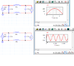
Filterr.JPG
In this circuit , the filter is used ithink its a PIe Filter
when i use 220V/50hz input then this filter gives me proper output .
but when im trying to use 115V/400Hz input then this filter gives me 0 output ( no output).
How can i change this filter for 400Hz ?
or what is the solution ?
 

Re: how can i change this filter for 400Hz ??

when im trying to use 115V/400Hz input then this filter gives me 0 output ( no output)
Technically impossible. If so, it's not the filter.
 

Some this go wrong during the simulation !!!!
The filter giving output for 50Hz should give output for 400Hz also.
Please check the values of L8, if the values are in Hentry there is huge attention for 400Hz. Find out the wrong thinks in simulation
400Hz.png
 

Status
Not open for further replies.

Part and Inventory Search

Welcome to EDABoard.com

Sponsor

Back
Top