Continue to Site

Welcome to EDAboard.com

Welcome to our site! EDAboard.com is an international Electronics Discussion Forum focused on EDA software, circuits, schematics, books, theory, papers, asic, pld, 8051, DSP, Network, RF, Analog Design, PCB, Service Manuals... and a whole lot more! To participate you need to register. Registration is free. Click here to register now.

How to monitor the battery voltage ?

Status
Not open for further replies.

Okada

Banned
Joined
Jun 16, 2016
Messages
1,159
Helped
129
Reputation
252
Reaction score
129
Trophy points
63
Activity points
0
How to monitor the battery voltage ?

See attached PDF for Circuit.


I have made this circuit. is this correct ?

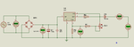
Lets assume that there is no mains power initially

So, the relay will be off (RL2 is relay, and RL1 is Solenoid).

This will connect 12V from battery to the Solenoid and to the input of 7805. 7805 will power the PIC. If

previous state of the solenoid was ON then PIC will turn it ON else it will be OFF.

The diode between 7812 and 7805 will block the battery voltage from flowing into the 7812 output pin.

BAT V pin is used to monitor the battery voltage. If batter voltage falls then solenoid is turned off.

Now, lets assume mains power returns.

Now MAINS SENSE pin is used to send the presence of mains voltage. If it is above 4.5V (for normal 230V AC

input) then it will turn ON the relay. When relay turns ON it will connect 12V from 7812 to Solenoid. Also when

mains power returns 7805 will be getting input from 7812 and 7805 will be powering PIC and hence the power to

PIC will not be interrupted durring relay turn ON.

L200C will charge the 12V 7 Ah battery at 1A rating.

D10 and D11 will reduce the voltage to 12V solenoid if battery voltage is say 13 or 13.5V in battery operation

mode.

Transformer is 0-15V 3A secondary.

Solenoid is Normally Closed 12V, 500mA.

TIP122 is 8A transistor. I need 2 or 3A transistor. What transistor can I use instead of TIP122 ?

How to monitor the BAT V because battery voltage will vary depending upon whether it is charging or discharging. The voltage divider used will not give proper value to adc input. Example when there is no mains the battery voltage might be 12V but when charging it might be 13.2V. So the voltage input to the voltage divider is different. How to measure ?

Should I use MAINS sense and use two different conditions for battery measurement like

if mains present use method 1 to measure the battery voltage
if mains not present use method 2 to measure battery voltage

I am using this valve.

https://www.sparkfun.com/products/10456

- - - Updated - - -

I will be using this battery.

https://www.amazon.in/APC-APC-RBC2-...id=1467885309&sr=8-1&keywords=apc+battery+12v

Can I safely charge this battery from 12V 1A (L200C output) ?
 

Attachments

  • Automatic Water Flow Control.PDF
    31.9 KB · Views: 121
Last edited:

Observations:

1. D6 probably isn't needed, if the intention is to lift the output voltage of the L200 by 0.6V, I would do it by adjusting RV1 instead.
2. I doubt you need D10 and D11, one or the other should suffice. The voltage to the solenoid isn't critical.
3. You need a capacitor from the input of U3 to ground for stability.
4. D2 (Green LED) runs at about (5-1.6)/1000 A = 3.4mA but D1 (red LED) runs at (12-1.4)/1000 A = 10.6mA. You might consider increasing R3.
5. TIP122 is fine, you can probably use a smaller transistor or a MOSFET but I see no problem with it as it is.
6. The ground connection is missing from the emitter of Q1
7. 'FLOAT SWITCH' should be pulled high to +5V, not the input of the 5V regulator!

For monitoring voltage, just scale the divider resistors so the maximum expected voltage, whether on charge or not, is just below the ADC reference. Be aware that if the battery is disconnected so there is minimal load on the transformer, the DC across C8 will rise to about 22V and be subject to variations in the AC supply. It might be safest to target the maximum divided voltage down to say 4.5V and connect a 4.7V Zener diode across it to protect the PIC. At the moment the 'MAINS_SENSE' voltage will be about 11V and the PIC internal pin protection will be forced to sink the excess which is not a good idea.

Brian.
 

Ok. here is the new Circuit.

1. I removed D6.
2. I also removed D10 and D11
3. I added a 1000 uF 16V at the input of U3.
4. My calculation was Red and Green LEDs take 2.1V and so for Green Led is (5-2.1)/330 = 8.7 mA and (12-2.1)/1k = 9.9 mA. Max current of LED is 20mA and 10 mA is 50% of the max limits.
5. Ok. I will use TIP122
6. Yes, I saw that and fixed it.
7. The Float Switch Connection was wrong. I fixed it. It uses a voltage divider. Input varies between 12 and 13.2 volts. Some 4.2 V is applied to FLOAT SWITCH input pin.

Ok. I will scale the divider resistor so the maximum expected voltage will be 15V. For C8 I will use a 470 uF 63V Capacitor. I will take that input to divider is 24V and accordingly scale the voltage for MAINS_SENSE and also I will use a 4.7V zener.


PIC internal pin protection will be forced to sink the excess which is not a good idea.

You mean the current through the MAINS_SENSE pin ?

But I am using high value resistance and current will be less than 1 mA through the adc input.

What about the APC Battery ? Can I safely charge it with 12 or 13V 1A ?

I referred these for the LED voltages.

http://dangerousprototypes.com/docs/Basic_Light_Emitting_Diode_guide

http://www.thedoityourselfworld.com/How-To-Properly-Use-LEDs.php
 

Attachments

  • Automatic Water Flow Control.PDF
    32.8 KB · Views: 148

3. I would suggest 1000uF is far too large, it isn't a reservoir for rectified AC like the input to U2 so you can use a much smaller value, I would try 10uF.

7. is still wrong. When the float switch is closed it will have 4.2V but when it is open the voltage goes up to 12V which can damage the PIC. All you have to do is use a single resistor as before but connect its top end to the output of the 5V regulator instead of the 12V one. The voltage will then go from zero to +5V as the switch opens.

You mean the current through the MAINS_SENSE pin ?
Yes, inside the PIC there are protective diodes between the pin and the VSS and the pin and VDD, they normally never conduct but if a voltage below VSS (a negative voltage) or higher than VDD is applied, the diode conducts and tries to divert the current away. If the transformer nominally produces 15VRMS, the voltage across C8 will be (sqrt(2)*15)-(2*Vf) = 20V and the 10K/10K divider will drop that to 10V. The maximum you are allowed at the ADC input is VDD so the protection diodes will be forced into conduction. Ideally you should make R15 a higher value so MAINS_SENSE never goes above 5V. The Zener gives extra protection in case of AC surges.

By coincidence, I used a battery identical to the APC one in a project yesterday! They should be charged at constant voltage of 13.4V and at a current no higher than 2.1A. If you set the voltage at 13.4V and limit the current to 1A it will be fine. On my project I used an LM317 regulator and a current limit of 0.2A as it is only a back-up lighting system.

Brian.
 
  • Like
Reactions: Okada

    Okada

    Points: 2
    Helpful Answer Positive Rating
3. Changed C7 to 10uF 16V.

7. Ok. Did as you mentioned.

Yes, inside the PIC there are protective diodes between the pin and the VSS and the pin and VDD, they normally never conduct but if a voltage below VSS (a negative voltage) or higher than VDD is applied, the diode conducts and tries to divert the current away. If the transformer nominally produces 15VRMS, the voltage across C8 will be (sqrt(2)*15)-(2*Vf) = 20V and the 10K/10K divider will drop that to 10V. The maximum you are allowed at the ADC input is VDD so the protection diodes will be forced into conduction. Ideally you should make R15 a higher value so MAINS_SENSE never goes above 5V. The Zener gives extra protection in case of AC surges.

Yes, I have not calculated the R15 and R16 because I don't know the value of the Transformer output voltage. I have ordered 4 transformers. I still have to get it.

I have ordered these transformers.

0-15V 3A
0-15V 5A
0-18V 3A
0-18V 5A

I will use the one of the 4 transformers and accordingly calculate the R15 and R16 values.

I added 4.7V 500mW Zener at MAINS_SENSE. Is it correct ?

By coincidence, I used a battery identical to the APC one in a project yesterday! They should be charged at constant voltage of 13.4V and at a current no higher than 2.1A. If you set the voltage at 13.4V and limit the current to 1A it will be fine. On my project I used an LM317 regulator and a current limit of 0.2A as it is only a back-up lighting system.

Ok. I got it.

See the attached circuit. I also added a 10uF 10V and 100nF16V across the PIC power pins and close to PIC power pins.

I added RL3 relay circuit. Is it necessary ? I have used it to protect battery from over-charging. If battery is fully charged then it will disconnect the input to L200 but if this is a good method then I want to know how to implement this that is at what battery voltage should I turn OFF this relay ? The relay will be initially ON (but in circuit shown as OFF).


I have used battery so that if works during power failures because Solenoid Valve is NC type. If There is power failure and water level is low and water is coming then without battery the valve will be closed and tank will not fill. Power failure is rare but I have taken that into consideration. So, I am worried about battery getting over-charged without RL3 relay.
 

Attachments

  • Automatic Water Inlet Control.PDF
    34.1 KB · Views: 132
Last edited:

@betwixt

Please see the attached circuit. I will be using 0-18V 5A Transformer for the Circuit. Should the open circuit voltage of L200CV be 13.4V or should it be 13.4 V when battery is connected ?

AC mains frequency is 50Hz and so the ripple DC frequency after bridge rectifier is 100 Hz. So, should I replace the 1000 uF with higher value capacitor like 22000 uF 63V. How to calculate the exact capacitor value at the input of L200 or any voltage regulator ?
 

Attachments

  • Batter Charger.png
    Batter Charger.png
    22.1 KB · Views: 91

I will be using 0-18V 5A Transformer for the Circuit. Should the open circuit voltage of L200CV be 13.4V or should it be 13.4 V when battery is connected ??

For max efficiency, you should use 15V 3A transformer; after rectification, it will be 15*1.4=21V- 2*(diode drop) but with full load it will drop down to around 16V or so.

If you fix the voltage, the battery will determine the current. If you fix the current, the battery will determine the voltage. You cannot fix both because the load is variable.

Max voltage 2.3*6=13.8V; typical 2.2*6=13:4V but you can leave it at a trickle charge with 2.1*6=12.6V.

Best way to charge batteries is to use a const current mode in the initial part till the voltage goes up to 13.8V and use trickle charge from that point. The const current must be selected based on the AH rating of the battery.

Special batteries have special needs.
 
  • Like
Reactions: Okada

    Okada

    Points: 2
    Helpful Answer Positive Rating
betwixt mentioned that The battery I am using should be charged at a constant voltage of 13.4V and Current not more than 2.1A. The battery mode is rarely used and hence it will not drain once it is charges and so shall I use constant voltage of 13.4V (adjusted after connecting the battery) and use lower current to charge the battery ?

What formula did you use to calculate the voltage after rectification ?

I am using the book "Fundamentals of Analog Circuits by Floyd and Buchla". In that it mentions if AC input is 5V(10V peak to peak) then after half wave rectification 0.7V drop across the diode and 4.3V appear at the output.
 
Last edited:

I am using the book "Fundamentals of Analog Circuits by Floyd and Buchla". In that it mentions if AC input is 5V (10V peak to peak) then after half wave rectification 0.7V drop across the diode and 4.3V appear at the output.

If the peak to peak voltage is 10V (-10V to +10V), after rectification it becomes 0 to 10V and the capacitor charges to the peak voltage of 10V. You need to subtract 2 diode drops from this value (1.4 or so; two diodes for each half cycle) and you will get 8.6V at no load. The voltage will drop with load and that will also depend on the filter capacitor. But the RMS value is independent of the filter capacitor: 8.6V peak voltage will be 8.6/sqrt(2)=8.6/1.4=6.1V.

But then if RMS value is 5V, the peak value will be 5*1.4=7V and not 10V. If you subtract 1.4V (diode drops), you will get 5.6V peak (no load at the filter capacitor) and this will correspond to 5.6/1.4=4V.

Therefore I do not know what the authors mean "AC input is 5V (10V peak to peak)"- most likely a mistake. Or, do they mean -5V to +5V?
 
  • Like
Reactions: Okada

    Okada

    Points: 2
    Helpful Answer Positive Rating
Yes, it is -5 to +5V. If measured using AC voltmeter it shows 5V.
 

AC voltmeters when fed with a sine wave will show the RMS voltage. When you rectify it and charge a capacitor, it will reach the peak voltage of the rectified sine wave which is 1.414 times the RMS voltage minus the voltage dropped in the recitifiers themselves. In a bridge rectifier there are always two diodes in series with the AC so you lose 2 times the Vf of each diode (about 1.4V).

Transformers are specified using RMS output voltage so expect 15V RMS to produce (15 * 1.414)-(2 * 0.7) = 19.81V DC and an 18V RMS transformer to produce (18 * 1.414)-(2 *0.7) = 24.05V DC. The actual transformer voltage pends on the AC voltage you feed it and the losses in it due to the load current so it's best to allow some safety margin in case of power 'surges'. If you target the voltage dividers for 20V or 24V and use Zener protection you should be safe.

That particular battery has a recommended charging voltage of 13.4V instead of the usual 13.8V for some reason. In real life it wouldn't make much difference which you used as long as the current is kept within safe limits.

Set the voltage to 13.4V before connecting the battery. As it charges the battery voltage will approach 13.4V and at that point no further current will flow. The current limit is there to protect the cells from overheating or gassing if 13.4V is applied and the actual cell voltage is much lower because the battery has discharged.

Brian.
 
  • Like
Reactions: Okada

    Okada

    Points: 2
    Helpful Answer Positive Rating
@Brian

Thank you. I will remove RL3 relay.

I have one more question. If I use 0-15V rms Transformer with bridge rectifier then I get 19.81V DC which is 3V above 12V which is the requirement for 7812 input. (I read that 7812 input must me 3V above its output voltage of 12V). So, can I go for 0-15V rms 5A transformer ?
 

Anyway 7812 cannot deliver 5A and you can certainly use a 0-15V 1A or perhaps 2A) transformer.
 

c_mitra has the advantage of being several time zones ahead of me :smile:

Yes, 15V should be more than adequate, if you use a higher voltage you just convert the extra to heat. The load current on the transformer is the sum of all the individual loads: the relays, LEDS, the micro and the battery being charged. As you are limiting the charge current and the other loads should be quite small, a 2A transformer is probably adequate. There is no harm in using a 3A one, it buys you a greater safety margin but it will be larger, heavier and probably more expensive.

Brian.
 

The max current of the load will be approx 800 mA and so I have chosen 7812 (500 mA Solenoid, 45 mA x 2 (2 relays), MCU some 100 mA. L200 is for battery charging and I will set charging current to max 800 mA.

When battery charging and Solenoid is ON current required will be approx 2A and hence I have chosen 3A or 5A transformer. I have 0-15V 3A relay but for testing I have also ordered 0-15V 5A transformer.
 

Status
Not open for further replies.

Part and Inventory Search

Welcome to EDABoard.com

Sponsor

Back
Top