Continue to Site

Welcome to EDAboard.com

Welcome to our site! EDAboard.com is an international Electronics Discussion Forum focused on EDA software, circuits, schematics, books, theory, papers, asic, pld, 8051, DSP, Network, RF, Analog Design, PCB, Service Manuals... and a whole lot more! To participate you need to register. Registration is free. Click here to register now.

What is the problem with the FM Transmitter circuit and my layout ?

Status
Not open for further replies.

jeolex

Member level 2
Joined
Jul 4, 2015
Messages
52
Helped
0
Reputation
0
Reaction score
0
Trophy points
6
Activity points
531
Dear friends.

I wanna make a fm transmitter with electret microphone for my elder aunt. We all live in same apartment, and sometimes my elder aunt need help. If we can listen her by our FM radio, when she need help, we can immediately go and help her. It was my main aim.

So I researched some circuit and I found one of them that seems solve my desire. Here website: http://www.talkingelectronics.com/projects/Spy Circuits/SpyCircuits-2.html

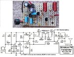
My circuit which I use it from website
DEVRE.gif
asd.png

NOT: Only different item from this circuit is Q1. I have used KTC9018 NPN transistor. I couldnt find 2N3563

My layout, I use Protheus ARES,
devre.jpeg

And my project as finished
WP_20160319_001.jpgWP_20160319_002.jpgWP_20160319_003.jpg

!!!_SO WHAT İS MY PROBLEM_!!!

I have tried this project. I have tuned FM radio that is empty, then adjust variable capacitor for finding the same frequency. But I couldnt get the clear sound from radio. Microphone is not so sensitive, I have to speak so close to microphone in order to get my voice. And also my voice is sizzling. When I move the circuit to anywhere, connection has lost.

I will be very pleasure if you help me.

Best regards.
 

PCB layouts like that don't work at high frequencies. The tracks work as inductors (think of them like a coil that has been un-wound) and as the frequency increases the amount of effect they have on the circuit becomes significant. You also have a problem with the orientation of the two coils, when they are close to each other and aligned the same way, they will magnetically couple to each other and the last transistor (feeding the antenna) may become an oscillator in it's own right instead of only being an amplifier.

Start your layout with a 'ground plane', make as much of the area as possible into copper ground. Most PCB packages have a facility to 'copper pour' or 'food fill' so all the available space is filled with copper and connected to one node, groud in your case. That does two things, it makes sure the best possible ground is available and it also provides a degree of screening from outside influences.

Also orientate the two coils at 90 degrees to each other, either rotated on the board surface or with one having its axis up and down, in other words you can look through it's middle to the board underneath it. That will reduce the amount of signal coupling between them and help to keep the circuit stable.

I would also move the capacitor across the battery to the other side so it is closer to the circuit. It's purpose is to ensure there is no signal on the supply line but at the moment you have the length of the tracks between the capacitor and the critical circuit that needs to have a clean supply.

If the frequency is tuning correctly but the microphone is insensitive, something is wrong around the first stage. Have you got the microphone the right way around? If you have a voltmeter, measure the voltage across the microphone and at each side of the 1M resistor with the meter negative probe to the negative side of the battery. I suspect the 22K resistor feeding the microphone may be too high in value when only using a 3V supply for it.

Brian.
 

I do not like the way the input transistor is dc biased. It is likely that transistor is fully saturated (collector voltage either at 0v DC or at 3V dc, instead of what it should be around 1.5 v DC). you can measure collector voltage with a voltmeter
 

If the BC547 input transistor has minimum hFE at 100 then for its collector voltage to be 1.5V and with a collector current of 1.5V/22k= 68uA then its base current must be 0.68uA. The voltage across the base bias resistor will be 1.5V - 0.58V= 0.92V then its value must be 0.92V/0.68uA= 1.35M.
If the BC547 has maximum hFE of 700 then the base bias resistor must be 9.47M.
Then I agree that the input transistor is probably saturated.

Your parts are too far apart for 100MHz. If the oscillator transistor is really a 2N3904 then its collector and emitter pins are connected backwards. Are your coils made with enamel insulated wire?
The circuit is missing pre-emphasis (treble audio frequencies boost) like all FM radio stations have then when heard on a normal FM radio that has de-emphasis (treble audio frequencies reduced) then it will sound muffled.

My FM transmitter has a good range and sounds great. It uses a 5V low-dropout regulator so that its preamp transistor always works properly and so that the oscillator frequency does not change as the battery voltage runs down. It has pre-emphasis. Its preamp transistor is biased with a voltage divider and has an emitter resistor so it does not change with different hFE. My output transistor has a tuned output and is fed from the emitter (not the collector) of the oscillator. I used a compact stripboard layout:
 

Attachments

  • FM tx mod4 pic and schematic.jpg
    FM tx mod4 pic and schematic.jpg
    196 KB · Views: 148

Status
Not open for further replies.

Part and Inventory Search

Welcome to EDABoard.com

Sponsor

Back
Top